UML
UML. unified modeling language. 1994 first attempts - largely theoretical 1997 UML becomes an industry standard ... ongoing evolution and efforts to standardize 2005 Nov.Dec. version 2.0 2007 Aug. version 2.1. general-purpose visual modeling language

UML
E N D
Presentation Transcript
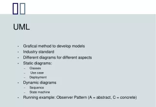
UML unified modeling language 1994 first attempts - largely theoretical 1997 UML becomes an industry standard ... ongoing evolution and efforts to standardize 2005 Nov.Dec. version 2.0 2007 Aug. version 2.1 • general-purpose visual modeling language • can be used from requirements engineering to implementation • for real-time embedded systems, management decision support • systems, high user interaction systems... • language and platform neutral but excellent support for • O-O languages (Smalltalk, Java, Python ...) • can be used with any SDLC methodology
UML unified modeling language diagrams: class classes, interfaces, relationships, collaboration object instances of things found in class diagrams use case modeling the behaviors of a system sequence time-ordering of messages collaboration structural organization of objects aka communication state chart event-ordered behaviour of objects aka state machine activity flow of control between objects component implementation view deployment run-time processing interaction overview of activity diagrams timing based on state chart diagrams composite structure depict internal structures package overview of class and other diagrams
functional requirements view from users' point of view static structural view objects, attributes, operations and relationships dynamic behaviour view collaboration among objects and changes to internal states of objects http://en.wikipedia.org/wiki/Unified_Modeling_Language
basic premise of UML we can model software and other systems as collections of collaborating objects dynamic model showing system behaviour object diagram Arlow, Neustadt. UML and the Unified Process: Practical Object-Oriented analsis and Design. Addison Wesley. 2002. fig. 1.6 adaptated use case diagram static model showing system structure sequence diagram collaboration diagram class diagram state chart diagram component diagram deployment diagram activity diagram
design view implementation view process view deployment view modeling a system’s architecture Booch, Jacobson, Rumbaugh. The Unified Modeling Language User Guide. Addison Wesley. 1999. fig. 2-20 vocabulary functionality system assembly configuration management use case view behavior performance scalability throughput system topology distribution delivery installation
some concepts • collaboration • objects work together in order to • provide the system functionality • communication • objects collaborate by sending messages to other objects • requesting the others to perform operations • association • objects have to know about other objects • in order to send these messages • responsibility • objects only contain data and methods relevant • to their own responsibilities
encapsulation other objects send messages requesting services an object's operations can only be called by a message with a valid operation signature an object's data can only be accessed by it's own operations the representation of an object's data is hidden inside