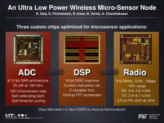
Sensor Node Architectures
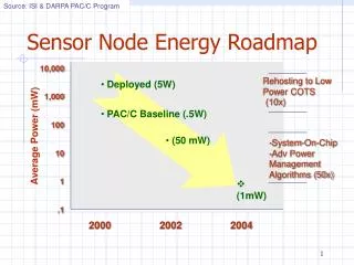
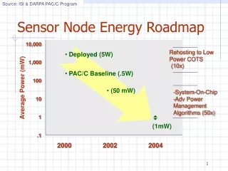
Sensor Node Architectures. EE202A Lecture Oct 1, 2003 Ram Kumar {ram@ee.ucla.edu}. Sensor Network Vision. Ack: Jason Hill, UC Berkeley. SENSING SUB-SYSTEM. PROCESSING SUB-SYSTEM. COMMUNICATION SUB-SYSTEM. ACTUATION SUB-SYSTEM. POWER MGMT. SUB-SYSTEM.

Sensor Node Architectures
E N D
Presentation Transcript
Sensor Node Architectures EE202A Lecture Oct 1, 2003 Ram Kumar {ram@ee.ucla.edu}
Sensor Network Vision Ack: Jason Hill, UC Berkeley
SENSING SUB-SYSTEM PROCESSING SUB-SYSTEM COMMUNICATION SUB-SYSTEM ACTUATION SUB-SYSTEM POWER MGMT. SUB-SYSTEM Sensor Node Architecture Components • Small physical size: 1 mm3 • Low Power Consumption: < 50 mW • Resource Constrained: 8 MHz, 4 Kb
Capabilities StarGate MK - II iBadge MICA Mote Size, Power Consumption, Cost Diversity in Platforms
Design Lineage of Motes • COTS dust prototypes (Kris Pister et al.) • weC Mote (~30 produced) • Rene Mote (850+ produced) • Dot (1000 produced) • Mica node ( 5000+ produced) • Mica2 (Current) • Spec (Prototype) Ack: Jason Hill, UC Berkeley
Processing Sub-System • Functions • Application Execution • Resource Management • Peripheral Interaction • Atmel AVR ATMEGA128L • RISC Architecture • 8 bit ALU/data-path • 128 Kb FLASH - Code • 4 Kb SRAM - Data • Multiple peripherals Details are available in the ATMEGA128L Datasheet
AVR Interrupts • Interrupts are triggers that can be used to monitor an event • One could use polling but, in most cases this has additional software overhead • Better to have the peripherals “interrupt” the controller when an event occurs ( e.g data availability, change of a condition etc) • Interrupts can be edge triggered (falling or rising edge) or level triggered (signal goes high or low) • On the AVR microcontroller, interrupts are vectored
AVR Timers Timer0 8 - bit • Multiple Timers • Multiple Clock Sources • CPU Clk • Real Time Clk – 32 KHz • Pre-scaled Clk from above sources • Multiple Interrupts • Timer Overflow • Output Compare • Functions • Periodic sampling pulses • Waveform generation Timer2 Timer1 16 - bit Timer3
AVR Peripherals • UART • Serial communication with the PC • SPI – Serial Peripheral Interface • Synchronous serial communication • Interface to Radio in the Mote • ADC • Analog – Digital Converter • Digitizing sensor readings • I/O Ports • General Purpose Input Output pins (GPIO) • Used to light up LEDs in Mote
AVR Power Management • Low Power operation – 15 mW @ 4 MHz • Multiple Sleep Modes • Sleep Modes: Shutdown unused components • Idle Mode – 6 mW • CPU OFF, all peripherals ON • CPU “woken up” by interrupts • Power Down Mode – 75 uW • CPU and most peripherals OFF • External Interrupts, 2 Wire Interface, Watchdog ON • Power Save Mode – 120 uW • Similar to Power Down • Timer0 continues to run “asynchronously”
Sensing Sub-System • Functions • Sampling physical signals/phenomena • Different types of sensors • Photo-sensor • Acoustic Microphone • Magnetometer • Accelerometer • Sensor Processor Interface • 51 Pin Connector • ON-OFF switches for individual sensors • Multiple data channels Sensors consume power Turn them off after sampling ! • Useful Link/Resources • The pin definitions of 51-pin connector • Check out the HW schematics • http://webs.cs.berkeley.edu/tos/ • Look under Hardware Designs tab • Details of other sensor boards • Check them out at the XBow website • http://www.xbow.com
Communication Sub-System • Functions • Transmit – Receive data packets wirelessly • Co-ordinate/Network with other nodes • Implementation • Radio • Modulation – Demodulation • Two types of radios: RFM, ChipCon CC1000 • RFM: Mica & predecessors • CC1000: Mica2 onwards • AVR • Protocol Processing
Wireless Comm. Basics • All wireless systems follow these steps • Radios have varying capabilities • RFM – Simple radio, only modulates-demodulates bits • CC1000 – Performs Machester coding-decoding and synchronization also
SPI RFM RADIO Data I/O SPI CLK Timer0 CTL0 CTL1 Mica - RFM AVR Interface • Data Interface • Periodic waveform generated by Timer0 • Waveform fed as clk to SPI unit • SPI samples Data I/O line periodically during Rx • SPI shifts out data during Tx • Radio only performs modulation-demodulation • Control Interface • GPIO Pins of AVR • Two Control lines decide • Radio state
SPI CHIPCON CC1000 RADIO Data I/O DCLK PCLK PDATA PALE Mica2 – CC1000 AVR Interface • Data Interface • SPI CLK generated by radio • Radio Rx data available as a bit-stream • Radio performs channel encoding-decoding • and bit-synchronization • Control Interface • GPIO Pins of AVR • Simulate SPI in S/W • PCLK: Program Clock • PDATA: Program Data • PALE: R/W Select • Radio state written to registers • in radio
Radio Power Management • Radio has very high power consumption • Tx power is range dependant - 49.5 mW (0 dBm) • Rx power is also very high - 28.8 mW • Power-down sleep mode - 0.6 uW • Above data for CC1000, 868 MHz (Check out CC1000 data-sheets for more numbers) • Radio power management critical • Idle state channel monitoring power = Rx Power • Put radio to sleep when not in use • But then, how do we know when somebody is trying to contact us ?
PALOS Medusa MK-II Overview ARM/THUMB 40MHz Running uCos-ii RS-485 & External Power ADXL 202E MEMS Accelerometer MCU I/F Host Computer, GPS, etc UI: Pushbuttons Ack: Andreas Savvides, NESL UCLA http://nesl.ee.ucla.edu/projects/ahlos/
References • Atmel ATMEGA128L DataSheet (www.atmel.com) • ChipCon CC1000 DataSheet (www.chipcon.com) • RFM TR1000 DataSheet (www.rfm.com) • XBow Corp. (www.xbow.com) • Jason Hill et. all, “System Architecture directions for Networked Sensors”, ASPLOS 2000 • Jason Hill et. all, “A wireless embedded sensor architecture for system-level optimization”, ISCA • Joe Polastre et. All, “Wireless Sensor Networks for Habitat Monitoring”, WSNA 2002 • TinyOS Web – (http://www.tinyos.net)