Digital Transmitter Implementation
This project focuses on the implementation of a digital transmitter utilizing LabVIEW and FPGA technology. We explored various modulation types including 4 DQAM and 8 DPSK. The hardware setup involved the NI 5761 Digitizer as the receiver and NI FlexRIO FPGA 7965R as both the transmitter and receiver, with additional DAC support from Tabor wx2182. Notably, we addressed performance bottlenecks due to DAC limitations over GPIB, emphasizing the importance of channel synchronization and efficient packet transmission. The project yielded insights into communication systems and identified key areas for future improvements.

Digital Transmitter Implementation
E N D
Presentation Transcript
Digital Transmitter Implementation Poster Winter 2011-2012 Barak Shaashua Barak Straussman Supervisor: IdanShmuel
Project Goals • Implementation of a transmitter with Labview on FPGA. • Project modulation types: • 4 DQAM • 8 DPSK
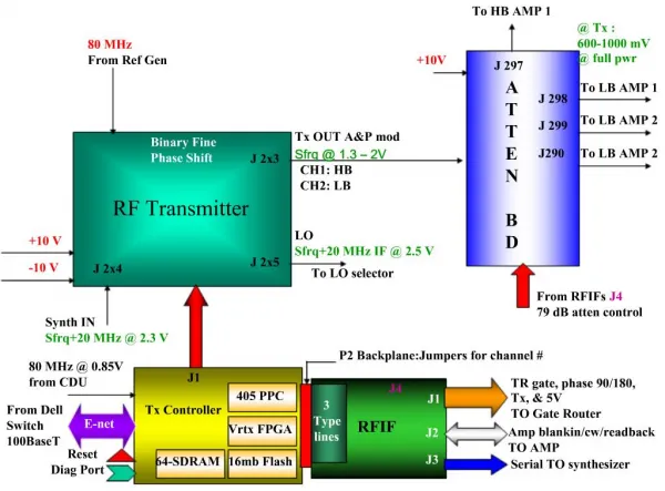
Hardware Connection NI 5761 Digitizer + NI FlexRioFPGA 7965R as RX NI FlexRioFPGA 7965R as TX • Tabor – wx2182 as DAC 2.1GS/s 250MS/s 16MB memory 1.5MB/s
System Problems • The bottleneck of the system is the speed of the DAC (Tabor wx2182) connection through the GPIB cable. • Therefore, the system complexity was reduced by simulating The TX on the HOST. (Even though the TX works on the FPGA). • Streaming is not supported by the DAC through the GPIB. Transmission is done in packets as big as the memory of the DAC. • The DAC doesn’t transmit both channels synchronically (without trigger). • As a result, the two channels are combined on the HOST and delivered to the DAC as one channel.
Data Rates • Transmitter boundary: DAC max sample rate: 2.1GS/sec. In this rate carrier wave frequency: 1.05GHz. • Receiver boundary: The ADC (NI5761) - max sample rate: 250MS/sec --> BW = 125MHz. • Data boundary: Limited by the DAC memory size - 16M samples.
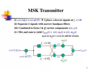
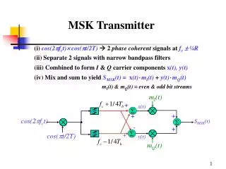
Transmitter Block Diagram I Source Coder Channel Coder Serial / Parallel Constellation Mapping Q DAC I + π/2 ISI Filter Up Converter Combiner Q Sin(wt) DAC
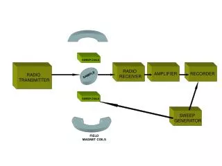
Receiver Block-Diagram LPF I Timing & Carrier Recovery + π/2 ADC RF Sin(wt) Q LPF I Channel Decoder Symbol Decision Constellation Mapping Parallel / Serial Q (+ Source)
Transmission Parameters • We worked with Carrier frequency: 50MHz + 10 samples per period --> DAC operates in 500MS/sec. • Symbol = 1 period of the carrier. • Data rate: DQPSK - 2 bit/symbol - 100Mbit/sec. D8PSK - 3 bit/symbol - 150Mbit/sec. • With 16M DAC memory - Data transition per transmission: 400KB (DQPSK) / 600KB (D8PSK).
Results • 25MHz transmission --> BER=0 (One symbol error at the edge, not dependent on transmission length) • 50MHz transmission --> BER=0 • 80MHz transmission --> BER=1/3 • No alignment between samples and carried periods. • Over sampling too low.
Summery • In this project we acquired a lot of knowledge about communication and modulation. • The project involved the integration of variety of systems and work environments. • Future improvements: • Labview - We found it hard to debug FPGA VI. • Tabor - In our project setting, wx2182 wasn’t suitable.