Download
1 / 76
800 likes | 1.05k Vues
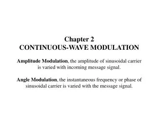
Chapter 2 CONTINUOUS-WAVE MODULATION Amplitude Modulation , the amplitude of sinusoidal carrier is varied with incoming message signal. Angle Modulation , the instantaneous frequency or phase of sinusoidal carrier is varied with the message signal. 2.1 Introduction

E N D
Chapter 2CONTINUOUS-WAVE MODULATIONAmplitude Modulation,the amplitude of sinusoidal carrier is varied with incoming message signal.Angle Modulation,the instantaneous frequency or phase of sinusoidal carrier is varied with the message signal.
2.1 Introduction Communication channel requires a shift of the range of baseband frequencies into other frequency ranges suitable for transmission, and a corresponding shift back to the original frequency range after reception. A shift of the range of frequencies in a signal is accomplished by using modulation, by which some characteristic of a carrier is varied in accordance with a modulating signal. Modulation is performed at the transmitting end of the communication system. At the receiving end, the original baseband signal is restored by the process of demodulation, which is the reverse of the modulation process. Figure 2.2 displays the waveforms of amplitude-modulated and angle-modulated signals for the case of sinusoidal modulation. Parts (a) and (b) show the sinusoidal carrier and modulating waves, respectively. Parts (c) and (d) show the corresponding amplitude-modulated and frequency-modulated waves, respectively.
Figure 2.2Illustrating AM and FM signals produced by a single tone. (a) Carrier wave. (b) Sinusoidal modulating signal. (c) Amplitude-modulated signal. (d) Frequency-modulated signal.
2.2 Amplitude Modulation Consider a sinusoidal carrier wave c(t) defined by c(t) = Accos(2fct) (2.1) where Ac is the carrier amplitude and fc is the carrier frequency. Let m(t) denote the baseband signal and the carrier wave c(t) is physically independent of the message signal m(t). An amplitude-modulated (AM) wave can be described as: s(t) = Ac[1 + kam(t)] cos(2fct) (2.2) where ka is the amplitude sensitivity of the modulator responsible for the generation of the modulated signal s(t). Figure 2.3a shows a baseband signal m(t), and Figures 2.3b and 2.3c show the corresponding AM wave s(t) for two values of amplitude sensitivity ka. The envelope of s(t) has essentially the same shape as the baseband signal m(t) provided that two requirements are satisfied:
Figure 2.3Illustrating the amplitude modulation process. (a) Baseband signal m(t). (b) AM wave for |kam(t)| < 1 for all t. (c) AM wave for |kam(t)| > 1 for some t.
1. The amplitude of kam(t) is always less than unity, that is, kam(t) < 1 for all t (2.3) This condition illustrated in Figure 2.3b ensures that 1+kam(t) is always positive, and the envelope of the AM wave s(t) of Equ. (2.2) can be expressed as Ac[1+kam(t)]. When the amplitude sensitivity ka of the modulator is large enough, |kam(t)| > 1, the carrier wave becomes over-modulated, resulting in carrier phase reversals whenever the factor 1+kam(t) crosses zero. The modulated wave then exhibits envelope distortion, as in Figure 2.3c. 2. The carrier frequency fc is much greater than the highest frequency component W of the message signal m(t), that is fc >> W (2.4) We call W the message bandwidth. If the condition of Equ. (2.4) is not satisfied, an envelope cannot be detected satisfactorily.
From Equ. (2.2), the Fourier transform of the AM wave s(t) is given by S(f) = (Ac/2)[d(f - fc) + d(f + fc)] + (kaAc/2)[M(f - fc) + M(f + fc)] (2.5) For baseband signal m(t) band-limited to the interval –W≦ f ≦W, as in Figure 2.4a, the spectrum S(f) of the AM wave is as shown in Figure 2.4b for the case when fc > W. This spectrum consists of two delta functions weighted by Ac/2 and occurring at ±fc, and two versions of the baseband spectrum translated in frequency by ±fc and scaled in amplitude by kaAc/2. From the spectrum of Figure 2.4b, we note the following: 1). the spectrum of the message signal m(t) for negative frequencies becomes visible for positive frequencies, provided the carrier frequency satisfies fc > W. 2). the AM spectrum lying above the carrier frequency fc is the upper sideband, whereas the symmetric portion below fc is the lower sideband. 3). the difference between the highest frequency fc + W and the lowest frequency fc - W defines the transmission bandwidth BT for AM wave: BT = 2W (2.6)
Figure 2.4(a) Spectrum of baseband signal. (b) Spectrum of AM wave.
AM VIRTUES AND LIMITATIONS • In the transmitter, AM is accomplished using a nonlinear device. Fourier analysis of the voltage developed across resistive load reveals the AM components, which may be extracted by means of a BPF. • In the receiver, AM demodulation is accomplished using a nonlinear device. The demodulator output developed across the load resistor is nearly the same as the envelope of the incoming AM wave, hence the name "envelope detector." Amplitude modulation suffers from two major limitations: 1). AM is wasteful of power. The carrier wave c(t) is independent of the information signal m(t). Only a fraction of the total transmitted power is actually affected by m(t). 2). AM is wasteful of bandwidth. The upper and lower sidebands of an AM wave are related by their symmetry about the carrier. Only one sideband is necessary, and the communication channel needs to provide only the same bandwidth as the baseband signal.
2.3 Linear Modulation Schemes In its most general form, linear modulation is defined by where sI(t) is the in-phase component and sQ(t) the quadrature component of the modulated wave s(t). In linear modulation, both sI(t) and sQ(t) are low-pass signals that are linearly related to the message signal m(t). Depending on sI(t) and sQ(t), three types of linear modulation are defined: 1). DSB modulation, where only the upper and lower sidebands are transmitted. 2). SSB modulation, where only the lower or the upper sideband is transmitted. 3). VSB modulation, where only a vestige of one of the sidebands and a modified version of the other sideband are transmitted.
Table 2.1 presents the three forms of linear modulation: 1). The in-phase component sI(t) is solely dependent on the message m(t). 2). The quadrature component sQ(t) is a filtered version of m(t). 3). Spectral modification of the modulated wave s(t) is solely due to sQ(t) .
DSB-SC MODULATION DSB-SC modulation is generated by using a product modulator that simply multiplies the message signal m(t) by the carrier wave Accos(2fct), as illustrated in Figure 2.5a. Specifically, we write s(t) = Acm(t) cos(2fct) (2.8) Figure 2.5c shows the modulated signal s(t) for the message waveform of Figure 2.5b. The modulated signal s(t) undergoes a phase reversal whenever the message signal m(t) crosses zero.
Figure 2.5(a) Block diagram of product modulator. (b) Baseband signal. (c) DSB-SC modulated wave.
The envelope of a DSB-SC signal is different from the message signal; unlike the case of an AM wave that has a percentage modulation < 100 %. From Equ. (2.8), the Fourier transform of s(t) is obtained as When m(t) is limited to the interval -W<f<W, as in Figure 2.6a, the spectrum S(f) of the DSB-SC wave s(t) is as illustrated in Figure 2.6b. Except for a change in scale factor, the modulation process simply translates the spectrum of the baseband signal by ±fc. DSB-SC requires the same transmission bandwidth as that for AM, namely, 2W.
Figure 2.6(a) Spectrum of baseband signal. (b) Spectrum of DSB-SC modulated wave.
COHERENT DETECTION The baseband signal m(t) is uniquely recovered from DSB wave s(t) by first multiplying s(t) with a locally generated sinusoidal wave and then low-pass filtering the product, as in Figure 2.7. The local oscillator signal is assumed coherent or synchronized with the carrier wave c(t) used in the product modulator to generate s(t). This scheme is known as coherent detection or synchronous demodulation. Denoting the local oscillator signal by Ac'cos(2fct + ), and using Equ. (2.8) for the DSB-SC wave s(t), the product modulator output in Figure 2.7 then is v(t) = Ac' cos(2fct + ) s(t) = Ac Ac' cos(2fct) cos(2fct + ) m(t) = (1/2)AcAc' cos(4fct + ) m(t) + (1/2)AcAc' (cos ) m(t) (2.10) The 1st term represents a DSB-SC signal with carrier frequency 2fc, whereas the 2nd term is proportional to the baseband signal m(t).
Figure 2.7Coherent detector for demodulating DSB-SC modulated wave.
It is further illustrated by the spectrum V(f) shown in Fig. 2.8, where it is assumed that the baseband m(t) is limited to -W<f<W. The 1st term in Equ. (2.10) is removed by the LPF in Figure 2.7, provided that the cut-off frequency of this filter is > W, but < 2fc - W. At the filter output we obtain a signal given by The demodulated vo(t) is proportional to m(t) when the phase error f is a constant. The amplitude of the demodulated signal is maximum when f = 0, and is minimum (zero) when f = ± p/2. The zero demodulated signals occur for f = ± p/2, represents the quadrature null effect of the coherent detector. The phase error f in LO causes the detector output to be attenuated by a factor of cos f. As long as the phase error f is constant, the detector provides an undistorted version of the original baseband signal m(t).
Figure 2.8Spectrum of a product modulator with a DSB-SC modulated wave as input.
QUADRATURE-CARRIER MULTIPLEXING The quadrature-carrier multiplexing or QAM scheme enables two DSB-SC waves to occupy the same channel bandwidth, and yet allows for the separation of the two message signals at the receiver output. It is a bandwidth-conservation scheme. A block diagram of the quadrature-carrier multiplexing system is shown in Figure 2.10. In Figure 2.10a, the transmitter involves two product modulators with the same carrier frequency but differing in phase by -90°. The transmitted signal s(t) consists of the product modulator outputs, s(t) = Acm1(t) cos(2pfct) + Acm2(t) sin(2pfct) (2.12) where m1(t) and m2(t) denote the message signals applied to the product mdulators. Thus s(t) occupies a channel bandwidth of 2W centered at the carrier frequency fc , where W is the message bandwidth of m1(t) or m2(t).
Figure 2.10Quadrature-carrier multiplexing system. (a) Transmitter. (b) Receiver.
According to Equ. (2.12), we may view Acm1(t) the in-phase and -Acm2(t) the quadrature component of the multiplexed bandpass signal s(t). The receiver part of the system is shown in Figure 2.10b. The multiplexed signal s(t) is applied to the two coherent detectors that are supplied with two local carriers of the same frequency but differing in phase by –90°. The output of the top detector is Acm1(t), and the bottom detector is Acm2(t). To maintain synchronization between local oscillators in the transmitter and the receiver, we may send a pilot signal outside the passband of the modulated signal. The pilot signal typically consists of a low-power sinusoidal tone whose frequency and phase are related to the carrier wave c(t).
SINGLE-SIDEBAND MODULATION In SSB modulation, only the upper or lower sideband is transmitted. We may generate such a modulated wave by the frequency-discrimination: • The first stage is a product modulator, which generates a DSB-SC wave. • The second stage is a BPF, which is designed to pass one of the sidebands of the modulated wave and suppress the other. The most severe requirement of SSB generation using frequency discrimination arises from the unwanted sideband. The nearest frequency component of the unwanted sideband is separated from the desired sideband by twice the lowest frequency component of the modulating signal. For SSB signal generation, the message spectrum must have an energy gap centered at the origin, as illustrated in Figure 2.11a. Assuming that the upper sideband is retained, the spectrum of the SSB signal is as shown in Figure 2.11b.
Figure 2.11.(a) Spectrum of a message signal m(t) with an energy gap of width 2fa centered on the origin. (b) Spectrum of corresponding SSB signal containing the upper sideband.
Three basic requirements in designing the BPF used in the frequency-discriminator for generating a SSB-modulated wave: • The desired sideband lies inside the passband of the filter. • The unwanted sideband lies inside the stopband of the filter. • The filter's transition band, which separates the passband from the stopband, is twice the lowest frequency component of the message signal.
To demodulate a SSB modulated signal s(t), we may use a coherent detector, which multiplies s(t) by a locally generated carrier and then low-pass filters the product. • This method of demodulation assumes perfect synchronism between the oscillator in the coherent detector and the oscillator in the transmitter. This requirement is usually met in one of two ways: • A low-power pilot carrier is transmitted in addition to the selected sideband. • A highly stable oscillator, tuned to the same frequency as the carrier frequency, is used in the receiver.
In the latter method, there would be some phase error f the local oscillator output with respect to the carrier wave used to generate the SSB wave. The effect is to introduce a phase distortion in the demodulated signal, where each frequency component of the original message signal undergoes a phase shift f. This phase distortion is tolerable in voice communications, because the human ear is relatively insensitive to phase distortion. The presence of phase distortion gives rise to a Donald Duck voice effect. In the transmission of music and video signals, the presence of this form of waveform distortion is utterly unacceptable.
VESTIGIAL SIDEBAND MODULATION In VSB modulation, one of the sidebands is partially suppressed and a vestige of the other sideband is transmitted to compensate for that suppression. VSB wave can be generated with the frequency discrimination method. First, we generate a DSB-SC modulated wave and then pass it through a BPF, as shown in Figure 2.12. It is the special design of the BPF that distinguishes VSB modulation from SSB modulation.
Figure 2.12Filtering scheme for the generation of VSB modulated wave.
Assuming that a vestige of the lower sideband is transmitted, the frequency response H(f) of the BPF takes the form shown in Figure 2.13. This frequency response is normalized, so that at the carrier frequency fc we have |H(fc)| = 1/2. The cutoff portion of the frequency response around the carrier frequency fc exhibits odd symmetry. In the interval fc - fv< | f | <fc + fv, the two conditions are satisfied 1). The sum of the values of the magnitude response |H(f)| at any two frequencies equally displaced above and below fc is unity. 2). The phase response arg(H(f)) is linear. That is, H(f) satisfies the condition H(f - fc) + H(f + fc) = 1 for –W<f<W (2.13)
Figure 2.13Magnitude response of VSB filter; only the positive-frequency portion is shown.
The transmission bandwidth of VSB modulation is BT = W + fv (2.14) where W is the message bandwidth, and fv is the width of the vestigial sideband. According to Table 2.1, the VSB wave is described in the time domain as s(t) = (Acm(t)/2)cos(2pfct) + (Acm'(t)/2)sin(2pfct) (2.15) where the “+” sign corresponds to the transmission of a vestige of the upper sideband, and the “-” sign corresponds to the transmission of a vestige of the lower sideband.
The signal m'(t) in the quadrature component of s(t) is obtained by passing the message signal m(t) through a filter having the frequency response HQ(f) = j[H(f - fc) - H(f + fc) for –W<f<W (2.16) Figure 2.14 displays a plot of the frequency response HQ(f). The quadrature component HQ(f) is to interfere with the in-phase component in Equ. (2.15) so as to partially reduce power in one of the sidebands of s(t) and retain simply a vestige of the other sideband. SSB may be viewed as a special case of VSB modulation. When the vestigial sideband is reduced to zero (i.e., we set fv = 0), the modulated wave s(t) of Equ. (2.15) takes the limiting form of a SSB wave.
Figure 2.14Frequency response of a filter for producing the quadrature component of the VSB modulated wave.
2.4 Frequency Translation SSB modulation is also referred to as frequency mixing, or heterodyning. Its operation is illustrated in the signal spectrum shown in Figure 2.11b compared to that of the original message signal in Figure 2.11a. A message spectrum from fa to fb for positive frequencies in Figure 2.11a is shifted upward by an amount fc in Figure 2.11b, and the message spectrum for negative frequencies is translated downward in a symmetric fashion.
Figure 2.11 (a) Spectrum of a message signal m(t) with an energy gap of width 2fa centered on the origin. (b) Spectrum of corresponding SSB signal containing the upper sideband.
A modulated wave s1(t) centered on carrier frequency f1 is to be translated upward such that its carrier frequency is changed from f1 to f2. This may be accomplished using the mixer shown in Figure 2.16. The mixer is a device that consists of a product modulator followed by a BPF. In Figure 2.17, assume that the mixer input s1(t) is an AM signal with carrier frequency f1 and bandwidth 2W. Part (a) of Figure 2.17 displays the AM spectrum S1(f) assuming that f1 > W. Part (b) of the figure displays the spectrum S'(f) of the resulting signal s'(t) at the product modulator output.
The signal s'(t) may be viewed as the sum of two modulated components: one component represented by the shaded spectrum in Figure 2.17b, and the other represented by the unshaded spectrum in this figure. Depending on the carrier frequency f1 is translated upward or downward, we may identify two different situations: Up Conversion:In this case the translated carrier frequency f2 is greater than the incoming carrier frequency f1, and the local oscillator frequency fL is defined by f2 = f1 + fL or fL = f2 - f1 The unshaded spectrum in Figure 2.17b defines the wanted signal s2(t), and the shaded spectrum defines the image signal associated with s2(t).
Figure 2.17 (a) Spectrum of modulated signal s1(t) at the mixer input; (b) Spectrum of the corresponding signal s'(t) at the output of the product modulator in the mixer.
Down Conversion:In this case the translated carrier frequency f2 is smaller than the incoming carrier frequency f1, and the required oscillator frequency fL is f2 = f1 – fL or fL = f1 - f2 The shaded spectrum in Figure 2.17b defines the wanted modulated signal s2(t), and the unshaded spectrum defines the associated image signal. The BPF in the mixer of Figure 2.16 is to pass the wanted modulated signal s2(t) and to eliminate the associated image signal. This objective is to align the midband frequency of the filter with f2 and to assign it a bandwidth equal to that of the signal s1(t).
2.6 Angle Modulation Angle modulation can provide better discrimination against noise and interference than amplitude modulation. This is achieved at the expense of increased transmission bandwidth; that is, angle modulation provides with practical means of exchanging channel bandwidth for improved noise performance. Let i(t) denote the angle of a modulated sinusoidal carrier, assumed to be a function of the message signal. The resulting angle-modulated wave is s(t) = Ac cos[i(t)] (2.19) where Ac is the carrier amplitude. If i(t) increases monotonically with time, the average frequency in Hz, over an interval from t to t + Dt, is given by
The instantaneous frequency of the angle-modulated signal s(t) is: According to Equ. (2.19), we may interpret the angle-modulated signal s(t) as a rotating phasor of length Ac and angle i(t). The angular velocity of such a phasor is di(t)/dt measured in radians/second. In the simple case of an unmodulated carrier, the angle i(t) is i(t) = 2pfct+ fc and the corresponding phasor rotates with angular velocity equal to 2pfc. The constant fc is the value of i(t) at t = 0.
Two common forms of angle modulation: 1). Phase modulation (PM),the angle i(t) is varied linearly with the message signal m(t), as shown by i(t) = 2pfct + kpm(t) (2.22) The term 2pfct represents the angle of the unmodulated carrier; the constant kp represents the phase sensitivity of the modulator, expressed in radians/volt. The angle of the unmodulated carrier is assumed zero at t = 0. The phase-modulated signal s(t) is thus described by s(t) = Accos[2pfct + kpm(t)] (2.23) 2). Frequency modulation (FM),the instantaneous frequency fi(t) is varied linearly with the message signal m(t), fi(t) = fc + kfm(t) (2.24) The term fc represents the frequency of the unmodulated carrier; the constant kf represents the frequency sensitivity of the modulator.
Integrating Equ. (2.24) with time and multiplying the result by 2p, we get where the angle of the unmodulated carrier wave is assumed zero at t = 0. • The frequency-modulated signal s(t) is therefore described by • Allowing the angle i(t) to become dependent on the message signal m(t) as in Equ. (2.22) or on its integral as in Equ. (2.25) causes the zero crossings of a PM signal or FM signal no longer have a perfect regularity in their spacing.
The envelope of a PM or FM signal is constant, whereas the envelope of an AM signal is dependent on the message signal. Comparing Equ. (2.23) with (2.26) reveals that an FM signal may be regarded as a PM signal in which the modulating wave is ∫m(t)dt in place of m(t). An FM signal can be generated by first integrating m(t) and then using the result as the input to a phase modulator, as in Figure 2.20a. A PM signal can be generated by first differentiating m(t) and then using the result as the input to a frequency modulator, as in Figure 2.20b.
Figure 2.20Relationship between FM and PM. (a) FM scheme by using a phase modulator. (b) PM scheme by using a frequency modulator.
2.7 Frequency Modulation Consider a sinusoidal modulating signal defined by m(t) = Amcos(2pfmt) (2.27) The instantaneous frequency of the resulting FM signal equals fi(t) = fc + kfAmcos(2pfmt) = fc + Df cos(2pfmt) (2.28) where Df = kfAm (2.29) The frequency deviation Df represents the maximum departure of the instantaneous frequency of the FM signal from the carrier frequency fc.
For an FM signal, the frequency deviation Df is proportional to the amplitude of the modulating signal and is independent of the modulation frequency. • Using Equ. (2.28), the angle qi(t) of the FM signal is obtained as • The ratio of the frequency deviation Df to the modulation • frequency fm, is commonly called the modulation index • of the FM signal: • b = Df / fm(2.31) • and • i(t) = 2pfct + bsin(2pfmt)(2.32)
From Equ. (2.32), the parameter b represents the phase deviation of the FM signal, the maximum departure of the angle i(t) from the angle 2pfct of the unmodulated carrier; hence, b is measured in radians. The FM signal itself is given by s(t) = Accos[2pfct + bsin(2pfmt)] (2.33) Depending on the modulation index b, we may distinguish two cases of FM: • Narrowband FM, for which b is small compared to one radian. • Wideband FM, for which b is large compared to one radian.