Robot Kinematics: Position Analysis - Matrix Representations, Transformations, and Kinematics Equations
400 likes | 700 Vues
Explore the fundamentals of robot kinematics in Chapter 2, including matrix representations of points, vectors, frames, and rigid bodies, as well as homogeneous transformation matrices. Learn about different types of transformations, such as pure translations, rotations about an axis, and combined transformations. Delve into the concepts of forward and inverse kinematics for robots, including Cartesian, cylindrical, spherical, and articulated coordinates. Understand the equations and principles behind determining the position and orientation of a robot's hand in space. This comprehensive guide provides a detailed overview of essential concepts in robot kinematics.

Robot Kinematics: Position Analysis - Matrix Representations, Transformations, and Kinematics Equations
E N D
Presentation Transcript
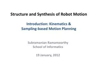
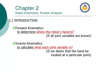
Chapter 2Robot Kinematics: Position Analysis 2.1 INTRODUCTION Forward Kinematics: to determine where the robot’s hand is? (If all joint variables are known) Inverse Kinematics: to calculate what each joint variable is? (If we desire that the hand be located at a particular point)
Chapter 2Robot Kinematics: Position Analysis 2.2 ROBOTS AS MECHANISM Multiple type robot have multiple DOF. (3 Dimensional, open loop, chain mechanisms) Fig. 2.1 A one-degree-of-freedom closed-loop four-bar mechanism Fig. 2.2 (a) Closed-loop versus (b) open-loop mechanism
Chapter 2Robot Kinematics: Position Analysis 2.3 MATRIX REPRESENTATION 2.3.1 Representation of a Point in Space A point P in space : 3 coordinates relative to a reference frame Fig. 2.3 Representation of a point in space
Chapter 2Robot Kinematics: Position Analysis 2.3 MATRIX REPRESENTATION 2.3.2 Representation of a Vector in Space A Vector P in space : 3 coordinates of its tail and of its head Fig. 2.4 Representation of a vector in space
Chapter 2Robot Kinematics: Position Analysis 2.3 MATRIX REPRESENTATION 2.3.3 Representation of a Frame at the Origin of a Fixed-Reference Frame Each Unit Vector is mutually perpendicular. : normal, orientation, approach vector Fig. 2.5 Representation of a frame at the origin of the reference frame
Chapter 2Robot Kinematics: Position Analysis 2.3 MATRIX REPRESENTATION 2.3.4 Representation of a Frame in a Fixed Reference Frame Each Unit Vector is mutually perpendicular. : normal, orientation, approach vector Fig. 2.6 Representation of a frame in a frame
Chapter 2Robot Kinematics: Position Analysis 2.3 MATRIX REPRESENTATION 2.3.5 Representation of a Rigid Body An object can be represented in space by attaching a frame to it and representing the frame in space. Fig. 2.8 Representation of an object in space
Chapter 2Robot Kinematics: Position Analysis 2.4 HOMOGENEOUS TRANSFORMATION MATRICES • A transformation matrices must be in square form. • It is much easier to calculate the inverse of square matrices. • To multiply two matrices, their dimensions must match.
Chapter 2Robot Kinematics: Position Analysis 2.5 REPRESENTATION OF TRANSFORMATINS 2.5.1 Representation of a Pure Translation • A transformation is defined as making a movement in space. • A pure translation. • A pure rotation about an axis. • A combination of translation or rotations. Fig. 2.9 Representation of an pure translation in space
Chapter 2Robot Kinematics: Position Analysis 2.5 REPRESENTATION OF TRANSFORMATINS 2.5.2 Representation of a Pure Rotation about an Axis Assumption : The frame is at the origin of the reference frame and parallel to it. Fig. 2.10 Coordinates of a point in a rotating frame before and after rotation. Fig. 2.11 Coordinates of a point relative to the reference frame and rotating frame as viewed from the x-axis.
Chapter 2Robot Kinematics: Position Analysis 2.5 REPRESENTATION OF TRANSFORMATINS 2.5.3 Representation of Combined Transformations A number of successive translations and rotations…. Fig. 2.13 Effects of three successive transformations Fig. 2.14 Changing the order of transformations will change the final result
Chapter 2Robot Kinematics: Position Analysis 2.5 REPRESENTATION OF TRANSFORMATINS 2.5.5 Transformations Relative to the Rotating Frame Example 2.8 Fig. 2.15 Transformations relative to the current frames.
Chapter 2Robot Kinematics: Position Analysis 2.6 INVERSE OF TRANSFORMATION MATIRICES Inverse of a matrix calculation steps : • Calculate the determinant of the matrix. • Transpose the matrix. • Replace each element of the transposed matrix by its own minor(adjoint matrix). • Divide the converted matrix by the determinant. Fig. 2.16 The Universe, robot, hand, part, and end effecter frames.
Chapter 2Robot Kinematics: Position Analysis 2.7 FORWARD AND INVERSE KINEMATICS OF ROBOTS Forward Kinematics Analysis: • Calculating the position and orientation of the hand of the robot. • If all robot joint variables are known, one can calculate where the robot is at any instant. •Recall Chapter 1. Fig. 2.17 The hand frame of the robot relative to the reference frame.
Chapter 2Robot Kinematics: Position Analysis 2.7 FORWARD AND INVERSE KINEMATICS OF ROBOTS 2.7.1 Forward and Inverse KinematicsEquations for Position Forward Kinematics and Inverse Kinematics equation for position analysis : (a) Cartesian (gantry, rectangular) coordinates. (b) Cylindrical coordinates. (c) Spherical coordinates. (d) Articulated (anthropomorphic, or all-revolute) coordinates.
Chapter 2Robot Kinematics: Position Analysis 2.7 FORWARD AND INVERSE KINEMATICS OF ROBOTS 2.7.1 Forward and Inverse KinematicsEquations for Position 2.7.1(a) Cartesian (Gantry, Rectangular) Coordinates IBM 7565 robot • All actuator is linear. • A gantry robot is a Cartesian robot. Fig. 2.18 Cartesian Coordinates.
Chapter 2Robot Kinematics: Position Analysis 2.7 FORWARD AND INVERSE KINEMATICS OF ROBOTS 2.7.1 Forward and Inverse KinematicsEquations for Position 2.7.1(b) Cylindrical Coordinates 2 Linear translations and 1 rotation • translation of r along the x-axis • rotation of about the z-axis • translation of l along the z-axis Fig. 2.19 Cylindrical Coordinates.
Chapter 2Robot Kinematics: Position Analysis 2.7 FORWARD AND INVERSE KINEMATICS OF ROBOTS 2.7.1 Forward and Inverse KinematicsEquations for Position 2.7.1(c) Spherical Coordinates 2 Linear translations and 1 rotation • translation of r along the z-axis • rotation of about the y-axis • rotation of along the z-axis Fig. 2.20 Spherical Coordinates.
Chapter 2Robot Kinematics: Position Analysis 2.7 FORWARD AND INVERSE KINEMATICS OF ROBOTS 2.7.1 Forward and Inverse KinematicsEquations for Position 2.7.1(d) Articulated Coordinates 3 rotations -> Denavit-Hartenberg representation Fig. 2.21 Articulated Coordinates.
Chapter 2Robot Kinematics: Position Analysis 2.7 FORWARD AND INVERSE KINEMATICS OF ROBOTS 2.7.2 Forward and Inverse KinematicsEquations for Orientation Roll, Pitch, Yaw (RPY) angles Euler angles Articulated joints
Roll: Rotation of about -axis (z-axis of the moving frame) Pitch: Rotation of about -axis (y-axis of the moving frame) Yaw: Rotation of about -axis (x-axis of the moving frame) Chapter 2Robot Kinematics: Position Analysis 2.7 FORWARD AND INVERSE KINEMATICS OF ROBOTS 2.7.2 Forward and Inverse KinematicsEquations for Orientation 2.7.2(a) Roll, Pitch, Yaw(RPY) Angles Fig. 2.22 RPY rotations about the current axes.
Rotation of about -axis (z-axis of the moving frame) followed by Rotation of about -axis (y-axis of the moving frame) followed by Rotation of about -axis (z-axis of the moving frame). Chapter 2Robot Kinematics: Position Analysis 2.7 FORWARD AND INVERSE KINEMATICS OF ROBOTS 2.7.2 Forward and Inverse KinematicsEquations for Orientation 2.7.2(b) Euler Angles Fig. 2.24 Euler rotations about the current axes.
Chapter 2Robot Kinematics: Position Analysis 2.7 FORWARD AND INVERSE KINEMATICS OF ROBOTS 2.7.2 Forward and Inverse KinematicsEquations for Orientation 2.7.2(c) Articulated Joints Consult again section 2.7.1(d)…….
Chapter 2Robot Kinematics: Position Analysis 2.7 FORWARD AND INVERSE KINEMATICS OF ROBOTS 2.7.3 Forward and Inverse KinematicsEquations for Orientation • Assumption : Robot is made of a Cartesian and an RPY set of joints. • Assumption : Robot is made of a Spherical Coordinate and an Euler angle. Another Combination can be possible…… Denavit-Hartenberg Representation
Fig. 2.25 A D-H representation of a general-purpose joint-link combination Chapter 2Robot Kinematics: Position Analysis 2.8 DENAVIT-HARTENBERG REPRESENTATION OF FORWARD KINEMATIC EQUATIONS OF ROBOT • Denavit-Hartenberg Representation : @ Simple way of modeling robot links and joints for any robot configuration, regardless of its sequence or complexity. @ Transformations in any coordinates is possible. @ Any possible combinations of joints and links and all-revolute articulated robots can be represented.
Chapter 2Robot Kinematics: Position Analysis 2.8 DENAVIT-HARTENBERG REPRESENTATION OF FORWARD KINEMATIC EQUATIONS OF ROBOT • Denavit-Hartenberg Representation procedures: Start point: Assign joint number n to the first shown joint. Assign a local reference frame for each and every joint before or after these joints. Y-axis does not used in D-H representation.
Chapter 2Robot Kinematics: Position Analysis 2.8 DENAVIT-HARTENBERG REPRESENTATION OF FORWARD KINEMATIC EQUATIONS OF ROBOT • Procedures for assigning a local reference frame to each joint: ٭ All joints are represented by a z-axis. (right-hand rule for rotational joint, linear movement for prismatic joint) ٭ The common normal is one line mutually perpendicular to any two skew lines. ٭ Parallel z-axes joints make a infinite number of common normal. ٭ Intersecting z-axes of two successive joints make no common normal between them(Length is 0.).
Chapter 2Robot Kinematics: Position Analysis 2.8 DENAVIT-HARTENBERG REPRESENTATION OF FORWARD KINEMATIC EQUATIONS OF ROBOT • Symbol Terminologies : ⊙ : A rotation about the z-axis. ⊙d : The distance on the z-axis. ⊙a : The length of each common normal (Joint offset). ⊙ : The angle between two successive z-axes (Joint twist) Only anddare joint variables.
Chapter 2Robot Kinematics: Position Analysis 2.8 DENAVIT-HARTENBERG REPRESENTATION OF FORWARD KINEMATIC EQUATIONS OF ROBOT • The necessary motions to transform from one reference frame to the next. (I) Rotate about the zn-axis an able of n+1. (Coplanar) (II) Translate along zn-axis a distance of dn+1 to make xn and xn+1 colinear. (III) Translate along the xn-axis a distance of an+1 to bring the origins of xn+1 together. (IV) Rotate zn-axis about xn+1 axis an angle of n+1 to align zn-axis with zn+1-axis.
Chapter 2Robot Kinematics: Position Analysis 2.9 THE INVERSE KINEMATIC SOLUTION OF ROBOT • Determine the value of each joint to place the arm at a desired position and orientation.
Chapter 2Robot Kinematics: Position Analysis 2.9 THE INVERSE KINEMATIC SOLUTION OF ROBOT
Chapter 2Robot Kinematics: Position Analysis 2.9 THE INVERSE KINEMATIC SOLUTION OF ROBOT
Chapter 2Robot Kinematics: Position Analysis 2.10 INVERSE KINEMATIC PROGRAM OF ROBOTS • A robot has a predictable path on a straight line, • Or an unpredictable path on a straight line. ٭ A predictable path is necessary to recalculate joint variables. (Between 50 to 200 times a second) ٭ To make the robot follow a straight line, it is necessary to break the line into many small sections. ٭ All unnecessary computations should be eliminated. Fig. 2.30 Small sections of movement for straight-line motions
Chapter 2Robot Kinematics: Position Analysis 2.11 DEGENERACY AND DEXTERITY • Degeneracy: The robot looses a degree of freedom and thus cannot perform as desired. ٭ When the robot’s joints reach their physical limits, and as a result, cannot move any further. ٭ In the middle point of its workspace if the z-axes of two similar joints becomes colinear. • Dexterity : The volume of points where one can position the robot as desired, but not orientate it. Fig. 2.31 An example of a robot in a degenerate position.
Chapter 2Robot Kinematics: Position Analysis 2.12 THE FUNDAMENTAL PROBLEM WITH D-H REPRESENTATION • Defect of D-H presentation: D-H cannot represent any motion about the y-axis, because all motions are about the x- and z-axis. TABLE 2.3 THE PARAMETERS TABLE FOR THE STANFORD ARM Fig. 2.31 The frames of the Stanford Arm.