Download
1 / 54
540 likes | 564 Vues
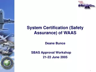
System Certification (Safety Assurance) of WAAS. Deane Bunce SBAS Approval Workshop 21-22 June 2005. System Certification. Verify Performance Requirements Met Accuracy Integrity Continuity Availability GAO Report of 2000

E N D
System Certification (Safety Assurance) of WAAS Deane Bunce SBAS Approval Workshop 21-22 June 2005
System Certification • Verify Performance Requirements Met • Accuracy • Integrity • Continuity • Availability • GAO Report of 2000 • FAA Underestimated Complexity of Proving the Integrity Requirement Satisfied • FAA Did Not Closely Monitor the Contractor’s Efforts to Demonstrate Integrity • Recommendations • Establish Checkpoints To Determine Contractor’s Approach For Meeting Performance Requirements • Have External Organization Evaluate Agency Progress At These Checkpoints
Approach for Assuring WAAS Integrity • Elements to Consider • WAAS Hazard Assessment • WAAS Architecture • Need for Technical Oversight (Independent Verification)
WAAS Architecture Satellite Signals • Correct – Then – Monitor Architecture • Trusted Processing for HMI Risk Limited to Safety Processors • Data Verification and Integrity Monitoring Algorithms Designed to Detect and/or Bound Sources of Data Errors • Must Verify System Architecture/Design Mitigates HMI Hazards or Reduces to Acceptable Risk • Safe Behavior Cannot Be Verified Completely Through Testing for Complex/Non-Deterministic Algorithms • System Integrity Performance Is Not Completely Quantifiable • Process-Based Assurance Method Required to Assure all Threats to Integrity were Addressed Corrections Processor Safety Processor Uplink/GEO Receiver User Monitors Data (Level B) Generates data (Level D) CRC protects data
Process Based Assurance Method • Safety Assurance: Assure that WAAS Design is capable of Meeting System Safety Requirements (Integrity and Continuity) • Method of Assurance Based on Aircraft Certification Standards / Prior Navaid Applications • SAE ARP 4754/4761, RTCA DO-178B • Consists of Audits/Reviews of Contractor System Development and Safety Assessment Activities • Process Captured in Safety Assurance Process Requirements Document [AVR/ATS]
Safety Assurance Process • Assurance Process: The Planned and Systematic Actions Necessary to Provide Adequate Confidence That a Product or Process Satisfies Given Requirements Safety Standards Mission Need Statement Safety Assurance MIL-STD-882 DO-178B Program Requirements Safety Assurance Requirements AVR ARP 4761/4754 Process Input System Development Plan System Safety Program Plan Assurance Guidance Integrity Threats System Development Safety Assessment ARP 4761 ARP 4754 Requirements Definition and Maintenance System Design Design Implementation and Integration Verification Hazard Analysis and Identification Requirements, Design, and Code Review Verification Review Design Requirements, Design , and Implementation Verification Methods and Results
System Development Activities • System and Component Development Activities to Assure Flow-down of Safety Requirements into the WAAS Implementation • System Engineering, Specification, and Architecture Design • Component Design Specification • Implementation and/or Procurement • Engineering Processes of Quality Assurance (QA), Configuration Management (CM) and Verification for All Development Activities
Safety Assessment Activities • System Hazard Assessment • Fault Tree Analysis • Algorithm P(HMI) Analysis • Safety Processor Input Analysis • Safety Directed Analysis • Exposure Time/Latency Analysis • Failure Modes and Effect Analysis (FMEA) • Common Cause Analysis • Safety Risk Assessment – HMI Hazards Sufficiently Controlled
Evidence Required • Plans and Standards • System and Component Specifications, Requirements, and Design Capture • System Safety Assessments • Component Implementation • System Integration • Acceptance Safety Assurance Process Requirements Artifacts Audits/ Reviews Vendor Vendor/FAA Baseline Reports/ Deliverables
Assurance Approval Process Safety Assurance Complete Safety Design Approval WIPP Approval Establish Baseline of Safety Artifacts Safety Assessments & Requirements Verification Monitor Development & Validation Complete
Assurance Approval • WAAS Program Office Establishes a WAAS Integrity Performance Panel (WIPP) • Role is to Establish Technical Approach and Solution for Meeting Integrity • WIPP Comprised of WAAS Experts … (FAA, Academia, Industry) • WIPP Meetings with Contractor Held Monthly to Review and Evaluate Contractor’s Progress
WIPP Tasks • Coding • Operating System • Computer HW • etc. Target Level of Safety Algorithm Contribution to HMI • A Great Stew of Feared Events Each Requiring: • Threat Model • Detection Algorithm • P(HMI) Analysis! SV 19 Level D SW WRS Clocks Iono Tropo L1/L2 Biases WRS RFI, Multipath Cycle Slips GPS Ephemeris
WIPP Role Algorithm Development Algorithm Definition Document (ADD) Coding Spec HMI Plan & Prelim Results Threat Model Monitor Design & Trades WIPP Approval WIPP Approval Evaluate with Field Data + Threat WIPPGuidance Operational Software Prototype & Validate Sys. Integ. Ready for Test Provability Assessment HMI Analysis WIPP Approval WIPP Approval Collect Data/Develop Tools WIPPGuidance DefineAnalysisMethodology Data- Driven Analysis HMI Analysis Report Prelim. Eval. Theoretical Analysis
WAAS Design Assurance • WAAS Design Assurance can be Broken down into Three Major Areas • Software Assurance • Hardware Assurance • Algorithm (Monitor) Assurance • Assurance that Hazards were Sufficiently Mitigated was Evaluated by Means of a Fault-Tree Analysis (FTA) • Events in Fault Tree Broken Down by Hardware, Software and Algorithm (Monitor) Contributions
Software Assurance Approach • Assurance Level Requirement Assigned According to RTCA/DO-178B Guidelines • Assigned According to the Hazard Severity Caused by Software Failure Based on the WAAS FTA • HMI – Assurance Level B (Where Software Failure is a Single Point Cause of HMI Without Mitigation or Control; or Software Function Provides Mitigation/Control of an HMI Failure Condition) • LOC – Minimum Assurance Level D (Where Software Failure is a Single Point Cause of LOC Without Mitigation or Control) • Software PHMI Contribution is Assigned Based on Assurance Level Achieved • HMI – Assurance Level B Software is Assigned a Failure Probability of Zero (0); Assurance Level D Software is Assigned a Failure Probability of One (1) • LOC – Assurance Level B or D Software is Assigned a Failure Probability of Zero (0) • Monitor Algorithms Failure to Detect Probability is Assessed Based on Probabilistic Analysis
Software Assurance – Alternate Means • Some Level D Functions Required Assurance • Developed a Process called Safety Directed Analysis (SDA) • Software Tested and Analyzed to Assure Output Always What is Expected • Result was Assignment of a Zero Probability for Failure in Fault Tree • Process and Results were Coordinated with FAA National Resource Specialist (NRS) for Software
Hardware Assurance • Assurance Completed at a Functional Level by means of a Failure Modes and Effects Analysis • Failure Rates of Hardware Utilized were Based on Several Years of Empirical Data • Exposure Times for Failures Captured as Part of Latency Analysis and Rolled into the Fault-Tree • Un-trusted Communications Assured by Means of Cyclical Redundancy Checks (CRCs)
Algorithm Assurance • Algorithms Developed to Detect Both Internal and External Faults • Internal Faults: • Data Provided to Monitors from Un-trusted Components was Assumed to be Corrupted • Required Analysis of all Inputs to the Safety Processor • Analysis Approach called Safety Processor Input Analysis (SPIA) Considered Corrupted Data, Absent Data and Data Timeliness and the Algorithms (Monitors) ability to Detect Such Conditions • External Faults or Environmental Conditions Evaluated by Means of an HMI Analysis Methodology
COTS Use on WAAS • Applied to Level D (or Lower) WAAS Functions • IBM AIX OS • Network Management Software • Compilers, CM Tools • Required to Meet All Applicable RTCA/DO-178B Objectives • Assured in Accordance with Allocated Functional Requirements Within the WAAS Application
Any combination of active data at user antenna causes MI and WAAS FTD within TTA LNAV-001 LNAV-001 WAAS GEO broadcasts a calculated underbound UDRE/GIVE leading to MI WAAS GEO broadcasts TSWM that got corrupted between WMS CMP and GUS WMP WAAS GEO broadcasts TSWM that got corrupted after Tandem CRC decoding WAAS GEO broadcasts TSWM that got corrupted after 24-bit CRC encoding and SLB FTD WAAS GEO broadcasts ranging signal that is MI WAAS GEO broadcasts valid UDRE that becomes MI LNAV-100 LNAV-200 LNAV-300 LNAV-400 LNAV-500 LNAV-700 WAAS Network FTA
GPS Satellite GEO Satellite SP1 SP2 32 BIT CRC 24 BIT CRC ETHERNET SWITCH ETHERNET SWITCH WRE-A (see figure A2 for details) TCS ANH- ROUTER TCS ETHERNET HUB ANH- ROUTER GPS ANTENNA WAAS RECEIVER COMPARATOR DCP COMPARATOR ETHERNET HUB CP1 WMP1 TCN BCN TCN BCN GUSP CP1 WSG RFU GPS ANTENNA WAAS RECEIVER WMP2 CP2 DCP WRE-B WRS x 25 (see figure A1 for details) SGS (see figure D for details) GUS WMS (see figure C for details) WAAS Network FTA LNAV-700 LNAV-500 LNAV-100 LNAV-200 LNAV-300 LNAV-400
WAAS GEO broadcasts TSWM that got corrupted after 24-bit CRC encoding and SLB FTD LNAV-400 G= 7.95E-23 WAAS GEO sent TSWM that got corrupted after 24-bit CRC encoding WMPs short loopback (SLB) FTD TSWM that got corrupted after 24-bit CRC encoding LNAV-401 LNAV-402 G= 2.12E-04 G= 3.75E-19 WAAS Network FTA – Data Transmission
WAAS Network FTA – SW Failure Bias error exists and Range Domain Monitor (RDM) FTD LNAV-114 G= 4.50E-08 Bias error exists leading to MI RDM FTD bias errors LNAV-192 LNAV-193 G= 1.00E+00 G= 4.50E-08 Note: LNAV-192 in this example is the result of any one of satellite L1-L2 bias error, receiver L1-L2 bias error, or receiver clock bias error. Since the error can result from untrusted software or hardware in any of these sources, the worst-case probability is used.
Safety Assurance Process Compliance Verification • FAA and Contractor Assure System Safety Program Plans (SSPPs) Address Safety Assurance Process Requirements • Contractor SSPP • Captures When and How Requirements are Satisfied • FAA SSPP • Schedule of Reviews Contingent on Contractor Plan • Establish Audit/Review Teams and Define Roles/Responsibilities • Seek Plan Approval • Safety Assurance Audit and Review Activity • Contractor Coordinates Artifact Schedule and Availability • FAA Verifies Artifact Compliance with SAPR • Completion of Activity Results in Safety Artifact Baseline
Safety Assurance Documentation Baseline • Established to Provide Evidence of Compliance with the WAAS Safety Assurance Process Requirements • Includes: • Program Planning and Standards Definition • System Specification, Requirements Definition, and Design • Component Specification, Requirements Definition and Design • System Safety Assessment • Component Implementation • System Integration • Configuration Management • Quality Assurance • Safety Assurance Process Compliance
Program Plans and Standards • System Engineering: System Engineering Management Plan, Reliability Program Plan • Software Engineering: Software Development Plan, PSAC, SAS and Supporting Process and Standards Notebooks • System Test: Master Test Plan, Development Test Plan, Production Acceptance Test Plan • System Safety: System Safety Program Plan, Supporting Process/Procedure Notebooks, Audit Records
System Specification and Design • System Specification • System Safety Architecture Description • Safety Requirements Traceability Matrix
Component Specification and Design • Prime Item Development Specifications • Software Requirement Specifications • Software Design Documents • Software Product Specifications • Algorithm Description Documents • WIPP Minutes
System Safety Assessment • System Hazard Analysis Report • Fault Tree Analysis • Algorithm Contribution to HMI • Safety Processor Input Analysis • Safety Directed Analyses • Qualitative Assessments • Failure Modes and Effects Analyses/Summaries (FMEAs/FMESs) • Failure Rate Source Documentation • Common Cause Analysis • Hazard Closure Records
Component Implementation • Hardware Test Plans, Test Procedures, and Test Reports • Software Test Plans, Test Procedures, and Test Reports • Software Test Folders/Regression Test Folders
System Integration • Design Qualification Test Procedures and Reports • Reliability Test Procedures and Report
Configuration Management • CM Plan • Configuration Audit Plan • Change Control Records • System Configuration Index
Quality Assurance • Quality Control Program Plan (or Quality System Plan) • Quality Audit/Review Logs
Safety Assurance Process Compliance • System Safety Program Plan • Safety Assurance Audit Process • Safety Audit Records • WAAS Safety Assurance Configuration Item List (SACIL) • Identifies List of Artifacts Required for Proof of SAPR Compliance • Defines Artifact Association to SAPR Requirements • Asserts Configuration Control over Artifacts Under Review • Creates and Maintains an Artifact Baseline Required for Formal Approval
Maintenance of WAAS Safety Baseline • Rationale for Safety Requirements a Must • Requirements Traceability • Baseline Definition and Control
System and Component Safety Assurance Reviews: • Specifications • System Architecture • Requirements • Designs • SW DO-178B Compliance • Procedures • Verification Procedures and Results • Validation Criteria • Configuration Conformance • QA Results Audits • Operating and Maintenance Procedures • Safety Assessment Safety Assurance Reviews: • Qualitative/Quantitative FTAs • Common Cause Analysis • FMEAs, FMESs, Failure Rates, Exposure Times • Procedures • Configuration Conformance • QA Results Audits • Program Plans and Standards Safety Assurance Reviews: • Plans and Standards • Verification Procedures • Verification Results • Configuration Conformance • QA Results Audits • Component Test Safety Assurance Reviews: • Test Procedures • Test Results • Validation Criteria • Configuration Conformance • QA Results Audits • System Integration Safety Assurance Reviews: • Test Procedures • Test Results • Validation Criteria • Configuration Conformance • QA Results Audits Quality Assurance Configuration Control Verification and Validation Reviews • System Safety Assessments: • Qualitative/Quantitative FTAs • Common Cause Analysis • FMEAs, FMESs, Failure Rates, Exposure Times • Procedure Assessments • System Integration: • As-Built Ssytem • SystemTest Procedures • Component Implementation: • As-Built Components • Test Procedures • System and Component Specification, Requirement, and Design Capture: • System Specifications • System Architecture • HW and SW Requirements • HW and SW Designs • Component Verification Procedures • Operating and Maintenance Procedures • Validation and Verification Procedures • Program Plans and Standards: • Configuration Control Plan • Quality Assurance Plan • Development Plans • Verification Plans • Acceptance Plan • Development Standards • Verification Procedures • Acceptance: • Deliverables • Conformance • Demonstration • Delivery Legend: Angled Arrows indicate data required for DO-178B Review = Safety Team Safety Assurance Activities = Intersecting Paths are Connected = Contractor Activities = Contractor Verification and/or Validation Activities = Intersecting Paths are not Connected = Contractor Configuration Control and Quality Assurance Activities System Development and Safety Assurance Process Model
Overview of Safety Assurance Activities End Qualitative HMI FT structure Design Level B SW Quantitative HMI FTA assurance review assurance DO-178B assurance review Safety directed analysis & test reviews compliance assurance review review VV/CC/QA VV/CC/QA Verif/Valid/CC/QA Qualitative Quantitative HMI FTA HMI FT structure Safety directed analysis & test of critical level D SW functions Verif / Valid/CC/QA VV/CC/QA SW component Procedural data mitigation assessment Other monitoring check data System architecture & functional descriptions Algorithm data Procedural mitigation cert review CRC data HW component data Verif / Valid/CC/QA HW HMI failure rates CRC failure rates Algorithm failure HMI FT base event from FMEA rates exposure times HMI FT base event Start Alg failure rates assurance review HW HMI FMEA CRC failure rates exposure times assurance review assurance review assurance review VV/CC/QA Legend: HMI FT base event probability calculations are = Data flow - intersecting pathes connected. = Safety team safety assurance activites. HMI FT base event = Raytheon activites. not = Data flow - Intersecting pathes are connected. probability calculations assurance reviews = Raytheon verification, validation, config control, & QA activities (placed behind corresponding Raytheon development activities)
PHMI Analysis - What Is It? • Probability of Monitor Missing an Error that would cause HMI has to be less than the assurance level (on order of 10-7) • DO-178B Level D inputs can NOT cause HMI when integrity monitor is operating as designed • Test 30 Days of WAAS Data (UDREI & GIVEI) for Overbounding • Evaluate Worst Case Convolutions of UDREI and GIVEI Histograms
P (MD error > cause hazard error enters monitor) < Allocation to Algorithm HMI From UDRE, GIVE message data determine protection level P(fail = 1) ~10-8 PHMI Analysis - How Does it Support FTA • Output of Algorithm PHMI Analysis Provides the Probability of Missed Detection based on a Fault free WAAS • SPIA, SDA, FMECA and Latency Analysis Provide Probability of Missed Detection based on Faulted WAAS (SDA and SPIA qualitative) 10-7 P(HMIE) + P(HMIEC)
SPIA - What is it? • Analysis that Determines the Erroneous Data Inputs that Could Result in HMI being Output from the Safety Processor (SP) • Define Inputs to each Monitor • Identify any Input or Combination of Inputs that Could result in HMI • Input data Conditions include: corrupted data, absent data or data timeliness • Determine if the fault condition(s) is covered by existing monitors • Determine the Dependency or Relation to Other Monitors • Backtracks the contributing data to the input source • Assess the likelihood for the contributing data being corrupted
SPIA - How does it support FTA? • SPIA Complements and Validates the FT • Identifies Events that Cause HMI • Verifies Events are Captured by FT; or • Contributes to FT Completeness • New Failure Event Identification • Qualitative Event Probability Assessment • Contributes to Resolution • No Action for Extremely Low Event Probability; or • Specific Identification of Level D Software Functions Which may be Assured by SDA; or • Need for Design Change to Mitigate Failure Event
SDA - What is it? • Qualitative Analysis of DO-178B Level D critical software functions identified in the WAAS fault tree • Critical Level D software functions are defined as those that prevent satisfaction of WAAS safety performance requirements • For Fault Tree Analysis, Level D software has a failure probability of 1 • Safety Directed Analysis is applied to the Level D software that performs these critical functions • The SDA demonstrates through analysis and test that software threats can be assigned a failure probability of 0 • Ensures that the Level D software is reliable enough to support the WAAS System safety performance
SDA - How Does it Support FTA? • Successful SDA Eliminates Software Failure Events from the Fault Tree • Failed SDA assessments will identify Level D functions that must be mitigated • Software design change will be implemented to monitor the Critical Level D function or rehost it to Level B • Fault Tree will be modified to incorporate the updated design and reduced PHMI
FMEA/FMES - What is it? • Failure Modes and Effects Analysis/Summary • Systematic, bottom-up method of identifying: • Failure modes of a system, component, or function and effects on next higher architecture level • Failure rate or probability of occurrence of failure modes at each level (limited to hardware on WAAS) • Also contains ability to detect severity of failure • May be performed at any architectural level • For WAAS most done at LRU level
ES hardware failures cause TSWM to be corrupted NPA054ES FTA ENB 1-6-30 (also doc’d in FMECA database) Event failure rate is the sum of the failure rates of the failure modes that map to it. Event probability is calculated from the event failure rate. Mapping of failure modes to events - implied ‘OR’ gate, sums failure rates for modes. Mapping documented in ENB 1-6-30. Failure mode failure rates are the sum of all the cause failure rates that map to the failure mode. FMECA Corrupted or intermittent data from port 1 of ES 1 . . . Corruption/noise in all external interfaces . . . Failure Modes Events in the FTA have one or more failure modes mapped to it. A group of such failure modes is called a Failure Mode Cluster. This cluster is CVES_WM:MI. Estimated MI failure rate from HPR database . . . FMEA/FMES - How Does it Support FTA? Data extracted from ENB 1-6-30C Figure 3.1-1