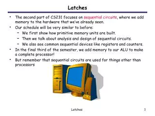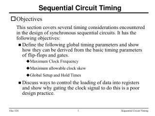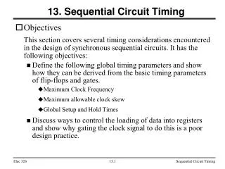
Understanding Sequential Circuits: Latches, Timing Issues, and J-K Latch Mechanics
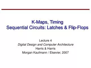
This session covers essential concepts in sequential circuits and latches as presented in Katz’s textbook. We will explore different types of latches, including the R-S and J-K latches, while emphasizing timing issues that influence circuit performance. Students will engage in in-class activities to identify the differences between combinational and sequential logic, analyze timing diagrams, and solve problems related to storage elements and race conditions. This comprehensive overview will provide the groundwork necessary for future studies in digital circuits and design.

Understanding Sequential Circuits: Latches, Timing Issues, and J-K Latch Mechanics
E N D
Presentation Transcript
Sequential Ckts, Latches and Timing Issues • Today: • First Hour: Sequential Circuits, Latches • Section 6.1.1 of Katz’s Textbook • In-class Activity #1 • Second Hour: J-K latch, Timing issues • Section 6.1.2-6.1.4 of Katz’s Textbook • In-class Activity #2
Combinational vs Sequential Logic Combinational logic circuits Circuits whose outputs are a function of their current inputs only Sequential logic circuits Circuits whose outputs are a function of their current inputs AND stored information about previous inputs Contain storage elements Contain feedback connections
INPUTS OUTPUTS Combinational network NEXT STATE Storage elements CURRENT STATE Sequential Switching Networks Block diagram of a sequential network
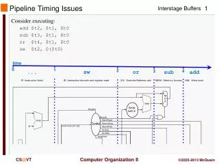
Y tpd Propagation Delay Let’s consider a buffer that has a propagation delay of tpd Y Suppose the input of the buffer is set to Y . After tpd seconds the output will be Y .
Feedback Suppose we connect the output to its own input a storage element! Y Y tpd If the input of the buffer is Y for at least tpd seconds, after tpd seconds the output becomes Y . Now, suppose we connect the output to its own input. Then this process is repeated indefinitely. It is independent of the value of Y !
tpd Buffers are usually implemented using a pair of inverters 1 2 1 2 tpd tpd Storage Elements
Y tpd tpd X R S Solution!! Replace the inverters with NOR gates 1 2 1 2 Storage Elements Problem!! No way to change the information
Y R X Q R S Q S R-SLatch Since X and Y are always complements, we rename them Qand Q The R-S Latch Redrawn to show symmetry
Q Q R-S Latch Walk-thru R=0 Q S=0 R=0 => invert S=0 => invert Q Result: Hold on to Q
R-S Latch Walk-thru R=1 Q=0 Q = 1 S=0 R=1 => Q = 0 (“reset function”) S=0 => invert Q Result: Reset Q to 0
Q Q R-S Latch Walk-thru R=0 Q=1 Q = 0 S=1 R=0 => invert S=1 => set to 0 Result: “set” Q to 1
Q Q R-S Latch Walk-thru R=1 Q S=1 R=1 => try to set Q to 0! S=1 => try to set to 0! Result: unstable race condition !
Functional truth table S R Q 0 0 Q hold 0 1 0 reset 1 0 1 set 1 1 unstable avoid Cross-Coupled NOR Gates This is the basis of current memory chips This device is called a latch
Timing Diagram Cross-Coupled NOR Gates R Q S \Q Timing Waveform Reset Hold Reset Set Race Set Forbidden State Forbidden State
Functional truth table Do Activity #1 Now S R Q 0 0 Q hold 0 1 0 reset 1 0 1 set 1 1 unstable avoid Cross-Coupled NOR Gates: R-S Latch R Q S \Q Timing Waveform Reset Hold Reset Set Race Set Forbidden State Forbidden State
The R-S Latch Next State Table Q+ is the next state: the state after input changes propagate to the outputs S R Q Q+ 0 0 0 0 0 0 1 1 0 1 0 0 0 1 1 0 1 0 0 1 1 0 1 1 1 1 0 NOT 1 1 1 ALLOWED What is the next state for these inputs? Use Don’t-Care for outputs of forbidden inputs ? ? X X
Functional behavior label HOLD The R-S Latch Next State Table S R Q Q+ 0 0 0 0 0 0 1 1 0 1 0 0 0 1 1 0 1 0 0 1 1 0 1 1 1 1 0 XNOT 1 1 1 XALLOWED RESET SET
Characteristic equation Q+ = S + R Q R-S Latch Characteristic Equation K-map for Q+ S R Q Q+ 0 0 0 0 HOLD 0 0 1 1 0 1 0 0 RESET 0 1 1 0 1 0 0 1 SET 1 0 1 1 1 1 0 X NOT 1 1 1 X ALLOWED QSR 00 01 11 10 0 0 0 X 1 1 1 0 X 1 Simplify !!!
Q E Q S Gated Latch Latch is level-sensitive, "clocked" by E R Latch operation enabled by E Outputs change when E is low: RESET and SET Otherwise: HOLD Input sampling enabled by gates
NEW !!! Eliminate the forbidden inputs Introduce “toggling” 1 TOGGLE 0 The J-K Latch NEXT STATE TABLE J K Q Q+ 0 0 0 0 HOLD 0 0 1 1 0 1 0 0 RESET 0 1 1 0 1 0 0 1 SET 1 0 1 1 1 1 0 1 1 1
The J-K Latch Schematic Latch Q K R Q’ Q J S Q
Characteristic equation Q+ = J Q + K Q J-K Latch Characteristic Equation NEXT STATE TABLE K-map for Q+ J K Q Q+ 0 0 0 0 HOLD 0 0 1 1 0 1 0 0 RESET 0 1 1 0 1 0 0 1 SET 1 0 1 1 1 1 0 1 TOGGLE 1 1 1 0 QJK 00 01 11 10 0 0 0 1 1 1 1 0 0 1 Simplify !!!
Timing Diagram Latch Q K R Q Q J S Q Reset Set Toggle Problem: Keeps toggling!
Clock a periodic external event (input) Clock SynchronousNetworks CLOCKED OUTPUTS INPUTS Combinational network NEXT STATE Storage elements CLOCK CURRENT STATE synchronizes when current state changes happen keeps system well-behaved makes it easier to design and build large systems
a high-to-low or low-to-high transition of the clock Hi-Lo edge Lo-Hi edge Clocking Event
Minimum time input is not changing before (setup time) and after (hold time) the clock event Tsu Th Clock event Setup Time & Hold Time There is a timing "window" around the clocking event during which the input must remain stable and unchanged in order to be recognized Input Clock
Due: End of Class Today RETAIN THE LAST PAGE (#3)!! For Next Class: Bring Randy Katz Textbook, & TTL Data Book Required Reading: Sec 6.1,6.3,7.1 of Katz This reading is necessary for getting points in the Studio Activity! Do Activity #2 Now