Download

1 / 20
200 likes | 406 Vues
SNS Timing System EPICS Workshop April 28, 2005 Coles Sibley Dave Thompson SNS Global Controls. Design Decisions. MPS and Timing systems are tightly integrated. Timing systems should “RESPECT” machine protection system beam power and pulse width limits to not “challenge” MPS system.

E N D
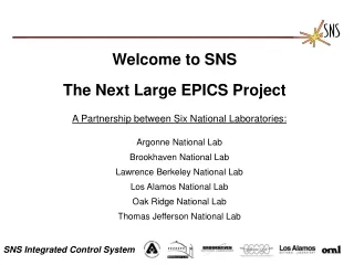
SNS Timing System EPICS Workshop April 28, 2005 Coles Sibley Dave Thompson SNS Global Controls
Design Decisions • MPS and Timing systems are tightly integrated. Timing systems should “RESPECT” machine protection system beam power and pulse width limits to not “challenge” MPS system. • Timing system will run at 60 Hz. (but don’t preclude the possibility of 120 Hz). • Super cycle will be 10 seconds (600 cycles, 0.1 Hz rep-rate resolution). • As much as possible should be done in hardware. • As little as possible should be relegated to the client IOCs. • Synchronous with Ring RF, not linac RF • System hardware design from RHIC
Machine Mode defines where the beam goes MEBT Beam Stop CCL Beam Stop Linac Dump Injection Dump Ring Extraction Dump Target Beam Mode defines allowable beam charge or power Pilot pulse (10 usec) Diagnostics pulse (50 usec) Tuning pulse (100 usec) Full Pulse Width (1 msec) Full Power (Depends on Dump) Machine / Beam Mode Definitions • Machine mode selected by Key switch in control room, Beam Mode selected by Key or software. Switches read by MPS PLC system and distributed through timing system.
GPS Timing System Components Event RTDL Link SNS Time Stamps Beam data Experimental Halls Master Timing IOC RF Gates Extraction Kickers TxHV Gates Timing SNS Real 10 MHz Slave Time Data Crystal (V124S) Link Osc. Master High resolution timestamps Machine Modes Machine SNS Event *32 PLL Protection Link (33 MHz) System Master Ring RF SNS Timestamps Remote Reset Synchronous ISR’s ICS IOC's Timing Reference Generator AC SNS Utility Module Line Beam Delay Beam Phase Micro pulse width Macro pulse width LEBT *4 PLL Chopper (64 MHz) Neutron Choppers SNS Time stamps Delays Gates Triggers Diagnostics Timing System Subsystem Hardware Hardware Timing System Users Experimental Systems
Timeline (from the timing system point of view) Informational Events, non critical timing Time Critical Events, (soft events disabled) Real-Time Data Link(RTDL) RTDL parameter transmission(for next cycle) RTDLTransmit Extract Beam On MPS Inhibit Snapshot, 1Hz, 6Hz, etc… MPS Fault (Alternate) Cycle Start RF & High Voltage Events End Injection Cycle Start System xxx Trigger Events Extraction Kicker Charge RTDL Valid Event Link Beam On Range Beam On Range Allowed Range for Variable Triggers Anytime Machine Anytime MPS Post Mortem Line-Synch Reference Clock beam accumulation -60 Hz ZeroCrossing +60 Hz ZeroCrossing 0 2 ms 4 ms 5 ms 6 ms 1 ms 3 ms 7 ms 8 ms
RTDL Sequencer • Runs at 60 Hz. Driven by the “RTDL Valid” Event interrupt. • Loads the RTDL frames for the next cycle (the cycle after the upcoming “Cycle Start” event, including: • Time of next Cycle Start (From GPS + ~162/3msec) for time stamps • Ring revolution frequency (from counter module) • Line crossing phase error (from timing reference generator) • Beam flavor parameters (Beam profile) • Machine and Beam Mode (MPS Mode Masking) • Last frame is 24-bit CRC on all RTDL data. • Writes correction term (based on measured event-link clock speed) to timing reference generator.
Event Link Sequencer • Runs at 60 Hz, driven by the “RTDL Valid” event. • Enables gates for variable rep-rate events that are scheduled to fire on the next machine cycle. • Handles the “bookeeping” tasks required for setting new rep-rates. Rep-Rate Pattern Generator • Actually, a set of EPICS “genSub” records. • Computes the rep-rate “patterns” used by the Event Link Sequencer to schedule which events should occur on each cycle. • Can also be used on “Client” IOC’s to do local rep-rates.
Inputs Desired Rep-Rate (double) Constraint Pattern (structure) V124S Gate Address (card & signal) Mode selector 0 = “Fixed” (ignore pattern) 1 = “Variable” (use pattern) Offset from Constraint Pattern (long) –n: Precede constraint pattern by n pulses +n: Follow constraint pattern by n pulses 0: No offset (pattern must be coincident with constraint pattern) Outputs Actual Rep-Rate (double) Rep-Rate Pattern (structure) Variable Rep-Rates — genSub Record Note: Constraint pattern can come from another “repRate” genSub record (e.g. for the gate this gate depends on) or from a combination of patterns (computed by another genSub record).
Application: Beam Control Hardware interface between MPS and Timing V124S Trigger Control Chassis Event Link } Auto Reset Latched MPS PLC MPS Inputs To Source Cycle Start Beam On To RFQ Source RF Delayed Source RF To Chopper RFQ From RFQ LLRF Controller
Event Link Monitor • Monitors event in a supercycle • Compare with event link sequence, fault on difference • Hardware check against software errors • Hardware read back for pattern generators
Application: Ion Source Control Warm LinacLLRF End Injection Extract Source RF Beam On Cycle Start Event Link Growth Source On Growth Delayed Source On RFQ Cycle Start Beam On 0 2 ms 4 ms 5 ms 6 ms 1 ms 3 ms 7 ms 8 ms
Application: Linac RF Control Requirements • RF Gates should always end at “End Injection” event. Increasing the gate width decreases the delay (and vice versa). • Low-level RF gate should come on about 100 mSec before beam (300 mSec in super-conducting linac). • HV power supplies should come on about 100 mSec before Low-Level RF. • Variable rep rates replaced with fixed events • 1, 2, 5, 10, 20, 30, and 60 Hz • Modulator HV Power supplies need an upgrade before 31 Hz or higher permitted • Individual RF gate widths adjustable but sets a constraint on maximum beam pulse width
Application: Linac RF Control RF Gate Relationships RF & High Voltage Events End Injection Extract Source RF Beam On Cycle Start Event Link Beam On Source On Warm LLRF Warm HPRF Cold LLRF Cold HPRF 0 2 ms 4 ms 5 ms 6 ms 1 ms 3 ms 7 ms 8 ms
Typical User Defined Beam Flavors • Reconfiguration requires beam off, flavor integrated charge and power recomputed, beam scheduled power calculated against machine/beam modes. • Flavors used by LLRF and Ring RF for feed forward loops. • 1 - Beam Off • 2 - 10 usec, (Chopped) (Fast faraday cup) • 3 - 50 usec , (Chopped) (All wire scanners, faraday cups) • 4 - 100 usec , (Chopped) • 5 - Physics , (Unchopped) • 6 – Arbitrary 1 msec gates, 50 usec beam • 7 - Reserved • 8 - Normal, ie. 1060 turns, 50 usec ramp up
Beam Profile Requirements • Ring Commissioning • 10 turns, 1 per 100usec (next generation of chopper) • Nominal beam to Linac Dump (Beam flavor 1) • Single turn (beam flavor 2) • Chopped beam to ring (beam flavor 3)
Pattern Generator – CD4 in 2006 • Fixed RF rep rates limited to < 30 Hz • 1 Hz beam, < 50 usec gate width thru Dec 2005 • LEBT Chopper commissioned, Beam gate < 1msec, integrated pulse width < 50usec • (LEBT fails with fulll width beam) • Beam RR and PW must fall in safe operating envelope (May 2006)
Beam Scheduling Post CD4 • SNS runs in loss limited mode (<10-4), Scale back in power until loss limits met. • All beam on after trip of > 5(?) min, pilot pulse and power ramp up required • Target has limits on machine trips, 25(?) fast and 5(?) slow per day. Requirements not defined for bad machine days. • Target Requirements • < 100 kW, no restrictions • > 100 kW and beam off < 30 min, no restrictions • > 100 kW and beam off > 30 min, linear ramp in power for 10 min. • One diagnostics pulse per super cycle allowed (Monitor injection phase painting) implies pulse to pulse scheduling. • Second target station, More pulse to pulse beam mode scheduling required
SNS AC Line is being Characterized using Filter for Neutron Chopper Response Six day line frequency measurement 60.1 Hz Line synch installed in controls lab timing system for distribution to neutron chopper lab. GPS-based filter with slew rate limit being studied 60.0 Hz Limiting Slew Rate results in wide frequency range 59.9 Hz 500usecs Deviation from Grid in usecs Deviation in slew rate in mHz/sec Beam Phase with line delay from 0 to 800 usec in 50 usec increments (2 beam trips) +/- 10deg RFQ Minimal Effect on Beam from 0 to 800usec delay
Use SLS and Diamond timing hardware (Timo Korhonen) 3 – D beam bunch shape measurements 12 degree longitudinal length, 402.5 MHz (83 psec) Need ~1 psec stability, 1 to10 psec resolution Use 402.5 or 805 MHz LLRF Reference line as input clock Synchronize Beam-On pulse using SLS Hardware New Requirements