Download
1 / 46
590 likes | 1.06k Vues
This chapter discusses various preparation techniques for synthetic membranes, including sintering, stretching, track-etching, and phase inversion. It explores the influence of different parameters on membrane morphology and presents techniques for composite membranes.

E N D
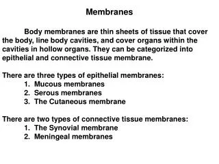
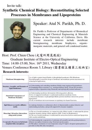
Preparation of Synthetic Membranes Chapter III (1) Introduction, III-1-2 (2) Polymeric membranes, III.3-5
Outline • Introduction • Preparation of synthetic membranes Sintering, Stretching, Track-etching, Template leaching, Phase inversion, etc. • Phase inversion membranes • Preparation techniques for immersion precipitation • Phase separation in polymer systems • Influence of various parameters on membrane morphology • Preparation techniques for composite membranes
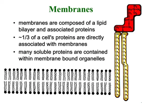
III. 1-2 Introduction Porous membrane Dense membrane Carrier membranes (gas separation/pervaporation) (microfiltration/ultrafiltration) Fig. III-1 Three basic types of membranes P71
Three basic types of membranes • Porous membranes • Separation depends on pore size and pore size distribution • Nonporous membranes • Separation depends on intrinsic properties of membranes • Thickness of the membrane matters!!! • Carrier mediated transport membranes • Separation depends on affinity and reactivity of membranes • Extremely high selectivity possible • Two types: mobile carrier & fixed site carrier …………….. …………….. ……………..
Membrane Material & Preparation Polymers: most common Inorganic: more stable hybrid Symemetric / Asymmetric / composite Sintering Sintering Stretching Stretching Track-etching Track-etching Template leaching Template leaching Sol-gel process Sol-gel process Solution coating Solution coating Phase inversion Phase inversion Ref: Mulder, Basic principles of separation technology
List of most important membrane preparation techniques • Sintering • Stretching • Track-etching • Template leaching • Sol-gel process • Phase inversion technique • Coating - Membrane modification
HEAT pore Sintering • Compressing a powder consisting of particles of given size and sintering at high temperatures. • For both polymeric and inorganic membranes with outstanding chemical, thermal and mechanical stability • Sintering temperature depends on the material (polymers, metals, ceramics, carbon, glass) • Pore size & distribution depends on the particle size & distribution (0.1-10µm) • Porosity 10-20%
Stretch extruded film perpendicular to the extrusion & crystallite orientation Only semicrystalline polymers (PTFE, PE, PP) used Rapture to make reproducible microchannels Pore size 0.1-3µm Porosity is very high (up to 90%) Stretching Stretched PTFE membrane
Thin membranes (up to 20µm) perpendicularly exposed to a high energy bean of radiation to break chemical bonds in the polymer The membrane is then etched in a bath which selectively attacks the damaged polymer. Features uniform cylindrical pores Pore size 0.02-10µm Surface porosity <10% Narrow pore size distribution Track-etching Track-etched 0.4 µm PCTE membrane
Membrane with capillary pores polymer film etching bath radiation source t0 t1 t2 t3 Track-etching process
Phase inversion A polymer transformed in a controlled manner from a liquid to a solid state • Phase inversion covers different techniques • For example: preparing asymmetric membranes: • A dense(r) skin layer integrally bonded in series with a thick porous substructure • Same material in each layer • The solidification initiated by the transition from one liquid state into two liquids (liquid-liquid demixing) • By controlling the initial stage of the phase transition the membrane morphology can be controlled.
III.3 Phase inversion techniques • Precipitation by solvent evaporation • Simple evaporation, coating • Precipitation from the vapour phase • Vapour phase: nonsolvent + saturatedsolvent • Prepare porous without top layer • Precipitation by controlled evaporation • Polymer dissolved in mixture of solvent and nonsolvent • Prepare membranes with skinned layer • Thermal precipitation • Polymer solution is cooled to enable phase separation • Prepare membranes with skinned layer • Immersion precipitation
III.4 Immersion precipitation • Polymer solution cast on a support (/or not) • Immersed in a coagulation bath containing a nonsolvent • Precipitation (solidification) occurs because of the exchange of solvent and nonsolvent • Membrane structure results from a combination of mass transfer and phase separation • Asymmetric membranes obtained- most commercial membranes prepared by this technique
1. Flat membranes GKSS equipment • Preparation parameters: • Polymer concentration (viscosity) • Casting thickness • Evaporation time • Humidity • Temperature • Additives (composition of the casting solution) • Solvent/solvents & non-solvent Fig. III-5 Preparation of flat sheet membranes
Factors affect membrane structure • Choice of polymer, choice of solvent/nonsolvent • Composition of casting solution • Composition of coagulation bath • Gelation and crystallization behavior of the polymer • Location of the liquid-liquid demixing gap • Temperature of the casting solution and coagulation bath • Evaporation time
Tubular form membranes Hollow fiber (d<0.5mm), self-support Capillary (d: 0.5-5mm), self-support Tubular (d>5mm), on support Techniques for preparation of HF and capillary membranes Dry-wet spinning (wet spinning) Melt spinning Dry spinning 2. Tubular form membranes
Spinning of hollow fiber membranes • Preparation parameters (dry-wet process) • Extrusion rate of the polymer solution • Flow rate of the bore fluid • Tearing rate • Residence time in air gap • Dimensions and types of the spinneret • Composition of polymer solution • Composition and temperature of coagulation bath
Membrane SEM images Fig 31.8 Hollow fiber membrane by phase inversion process, using high elongational draw ratios to elimiate macrovoids, reduce fiber dimension and increase fiber production Ref. TAI-SHUNG NEAL CHUNG, Chapter 31, FABRICATION OF HOLLOW-FIBER MEMBRANES BY PHASE INVERSION, in Advanced membrane technology and application.
Lab-scale spinning rigs in Memfo Ref.: Xuezhong He Blog
Tubular membrane preparation P81 Fig.III-9 Tubular membrane preparation
III.6 Phase separation in polymer system General thermodynamic description of the phase separation • Polymer-solvent-nonsolvent ternary system • From stable homogeneous polymer solution to demixing • Solvent and nonsolvent miscible • If the solvent is removed from the mixture at the same rate as the nonsolvent enters, the composition of the mixture will change following the line A–B. • A, casting solution; • B, membrane porosity; • B’, polymer-lean phase; • B’’, polymer-rich phase Qualitatively, not quantitatively described! Ref. H Strathmann, L Giorno and E Drioli,1.05 Basic Aspects in Polymeric Membrane Preparation in book Comprehensive membrane science and technology
Relationships among dope composition, precipitation kinetics, & membrane morphology Delayed demixing - dense toplayer Instantaneous demixing – microporous toplayer Ref. TAI-SHUNG NEAL CHUNG, Chapter 31, FABRICATION OF HOLLOW-FIBER MEMBRANES BY PHASE INVERSION, in Advanced membrane technology and application.
III.7 Influence of parameters on membrane morphology • Choice of solvent/nonsolvent system • The polymer concentration • The composition of the coagulation bath • The composition of the polymer solution • The use of additives • The temperature of the polymer solution and of the coagulation bath
Choice of solvent/nonsolvent system Fig.III-44. Delay time of demixing for 15% cellulose acetate/sovent solution in water, P127 Delayed demixing - dense toplayer Instantaneous demixing – microporous toplayer Figure. Asymmetric membrane with a dense top layer (a) and a porous top layer (b), Ref. Braz. J. Chem. Eng. vol.28 no.3 São Paulo July/Sept. 2011
Classification of solvent/nonsolvent P129 In general • High mutual affinity pairs – • Instant demixing • porous • Low mutual affinity pairs – • Delayed demixing • nonporous
Polymer concentration • Higher concentration results in • lower top layer porosity, thicker top layer P130 P131 Fig.III-46 Calculated composition paths for the system CA/dioxan/water for varying CA concentrations in the casting solution
Factors promotes the formation of porous membrane • Low polymer concentration • High mutual affinity between solvent and nonsolvent • Addition of nonsolvent to the polymer solution • Vapour phase instead of coagulation bath • Addition of a sencond polymer
Formation of integrally skinned membranes • Toplayer: thin & defect-free • By delayed demixing • Sublayer: open with negligible resistance • By instantaneous demixing • Generate a polymer concentration profile (as Fig III-51): • By introducing an evaporation step before immersion • Immersion in a nonsolvent with a low mutual affinity P135 Fig.III-51 Volume fraction of polymer in the casting solution after a short period of time
Formation of macrovoids • Porous sublayer - part of an asymmetric membrane • Factors that favours the formation of porous membranes also favours the formation of macrovoids • Instantaneous demixing • A high affinity between the solvent-nonsolvent • Polymer poor phase - macrovoids • Weak spot for membranes for high pressures Ref. http://www.polyu.edu.hk/riipt/tech-platforms/biosensing.html
Effects of tear rate Fig 31.8 Hollow fiber membrane by phase inversion process, using high elongational draw ratios to eliminate macrovoids, reduce fiber dimension and increase fiber production Ref. TAI-SHUNG NEAL CHUNG, Chapter 31, FABRICATION OF HOLLOW-FIBER MEMBRANES BY PHASE INVERSION, in Advanced membrane technology and application.
To prepare composite membranes Dense top layer (defect-free, ultrathin) Porous support (low resistance –surface pores) Coating techniques: Dip-coating spray coating spin coating Plasma polymerization Interfacial polymerization In-situ polymerization Coating Ref: Mulder, Basic principles of separation technology
Sample dip-coating membrane Top layer porous support Porous support non-woven support
Composite membrane Dense layer on porous substrate of different materials Each layer can be optimized Materials for selective layer are not limited (mechanical, chemical, thermal stability, processibility, etc.) Applications: RO, GS, PV Preparation techniques Dip-coating Spray coating Spin coating Interfacial polymerization In-situ polymerization Plasma polymerization Grafting III.5 Preparation techniques for composite membranes
Dip-coating • Dip & controlled evaporate • Post-treatment • Cross-linking • Heat treatment • Main effects on coating thickness • Coating velocity, viscosity, types of polymers, types of solvent and concentration of polymers • Equilibrium thickness: (III-1) p85
State of polymers Glassy: coating may rupture during evaporation (Tg passed) Rubbery: mostly defect-free coating Solvent Good solvent-larger coil Poor solvent-polymer aggregate Entanglement during evaporation Hydrophilic vs. hydrophobic support surface Dip-coating considerations
Dip-coating considerations • Pore penetration • Capillary force may cause pore penetration of solution • Resistance increases due to the blocked pores • Methods to avoid pore penetration • Pre-filling the pores • Chose polymer of higher MW • Chose support of smaller pores • Narrow pore size distribution • Match surface tension of the solution to the support membranes
Spray coating An example Also for polymeric membranes in solution
Interfacial polymerization Thickness<50nm P82 Fig. III-10 The formation of a composite membrane via interfaciaol polymerisation
Plasma polymerization:Plasma (physics & chemistry) • Plasma: a state of matter similar to gas, in which a certain portion of the particles is ionized • Charged particles: equal positive ions and negative ions/electrons • Ionization is generally accompanied by the dissociation of molecular bonds • Ionization methods: • Heating • Applying strong electromagnetic field with a laser or microwave generator Glow Discharge
Plasma polymerization • Plasma polymerization refers to formation of polymeric materials under the influence of plasma (also termed as Glow Discharge Polymerization) • Plasma polymer films can be easily formed with thickness of 0.05m. • These films are highly coherent and adherent to variety of substrates like conventional polymers, glass, metals. • Films are highly dense & pinhole free. • Multilayer films or films with grading of chemical and physical characteristics can be easily prepared . • One step process .