Download
1 / 30
440 likes | 900 Vues
This chapter explores the preparation of inorganic membranes, including types such as ceramic, zeolite, glass, metal, and carbon membranes. It covers the advantages and disadvantages of inorganic membranes over polymeric ones, the sol-gel process, membrane modification, and various inorganic composite membranes. The text delves into the synthesis methods, pore sizes, materials used, and applications of inorganic membranes, highlighting their high thermal and chemical stability, biocompatibility, and long lifetime. While inorganic membranes offer several advantages, they also pose challenges such as high capital costs, brittleness, and complex preparation methods.

E N D
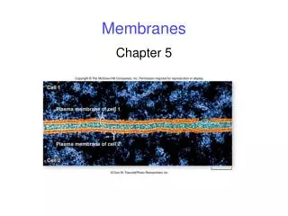
Preparation of Synthetic Membranes Chapter III (3) Inorganic membranes II-17, III-8, & reference (4) Hybrid membranes
Outline • Introduction • Types of inorganic membranes • Advantages/disadvantages over polymeric membranes • General scheme for the preparation of inorganic membranes • Sol–gel process • Membrane modification • Zeolite membranes • Glass membranes • Metal membranes • Carbon membranes
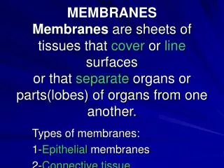
Types of inorganic membranes Ceramic membranes Zeolite membranes Glass membranes Carbon membranes Metallic membranes Ref. Internet resources
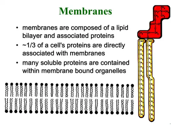
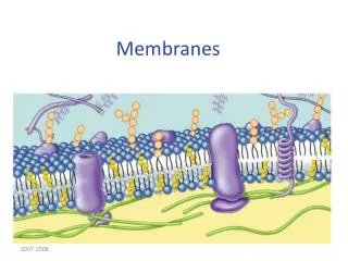
Inorganic membranes- materials • Ceramic membranes: • Mainly various oxides of alumina, titania or zirconia • By sol-gel process • Metal membranes: • palladium, silver and their alloys • Carbon membranes • Glass membranes • Silicon oxide or silica, SiO2 , by leaching on demixed glasses • Zeolite membranes • Ordered porous, narrow pore size
Inorganic membranes: morphology • Symmetric & Asymmetric • Dense membranes • Porous membranes • Ordered porous membranes • Zeolites • mesoporous silica • MOF structures • Composite membranes Ref. Dr. Lai. presentation
Inorganic composite membrane Critical Separation (selective) Layer(s)Pore Size: 0.4-5nm Thickness: single or multiple thin layersMaterials: OxidesUses: RO, nanofiltration & molecular sieving Primary LayerPore Size: 0.005-0.5 µmThickness: 1-20 µmMaterials: oxides, carbides, nitrides, metals, metal alloys, and carbonUses: Ultrafiltration & microfiltration Porous Support/SubstratePore Size: 0.5-50 µmThickness: >400 µmMaterials: Metals, metal alloys, oxides, carbides, nitrides, intermetallicsUses: Depth filter & surface-cake filter
Advantages of inorganic membranes • High thermal stability • Compatible with high-temperature operations, membrane reactors. • High chemical stability • good corrosion resistance, allowing very aggressive cleaning, • Biocompatibility • Pharmaceutical and food industry. • Not compact under high pressures • High mechanical strength • Long lifetime
Disadvantages of inorganic membranes – in general • High capital costs • Brittleness • Low membrane surface per module volume • Complex preparation methods • Difficult membrane-to-module sealing at high temperatures • Difficult to scale up • Poor reproducibility
Synthesis of inorganic membranes, Ref: 1.11 Basic Aspects in Inorganic Membrane Preparation in Comprehensive membrane science and engineering, Enrico Drioli and Lidietta Giorno, Volume 1, 2010, Elsevier
III.8.1 The sol-gel process Sol–gel is a general process which converts a colloidal or polymeric solution (sol) to a gelatinous substance (gel). • Sol-gel involves the hydrolysis and condensation of alkoxide or salt precursors in an organic solvent with an appropriate amount of water. • Preparation of ceramic membranes of different shapes with a mesoporous structure (~100nm) • Thick films/ Thin films/ Fibers Sol is a colloidal suspension (microscopically dispersed evenly) of very small solid particles in a continuous liquid medium. Examples include blood, pigmented ink, and paint. Gel can be defined as a 3-D network structure, and the compactness of the structure depends on the pH, concentration and natural of ions to stabilize the colloid suspension
Sol-gel process & shaping Ref: http://en.lswn.it/
Two sol-gel routes • Colloid suspension route • Polymeric gel route • Process: • Hydrolysis + condensation (polymerization) of a precursor • Required membrane structure can be controlled by process conditions • Drying is critical in the formation of membranes P143
Two main sol–gel routes Hydrolysis Condensation
Colloid suspension route: • Sol solution: precise control of the hydrolysis & condensation conditions (precursor concentration, and acid or basic catalysis, etc.) • Membrane pore size depends on the conditions of the hydrolyzing / condensation process and of the calcination temperature. • Rapid hydrolyzing & condensation with excess of water • The rapid condensation causes the formation of medium-sized nanoparticles of the order of 20–100nm • Addition of organic binder materials to relax the stress during drying (e.g. PVA) • Sol coated to obtain certain shape of membranes • Coated on support with top layer pores in the order of the sol particles. • Gelling of the sol, formed membrane dried and calcined at an appropriate temperatures
Polymeric sol–gel route: Producing fine pores of microporous membrane layers • Same precursors, but only partially hydrolyzed • using less than the stoichiometric amount of water • Hydrolysis is kept slower • Polymeric sol is transparent • containing small nanometersized inorganic polymeric structures < 5nm • Coating the support and interlayer without any binder • binders create very large voids in the coated layer after thermal treatment. • A polymeric network forms (gel) Ref: http://www.solgel.com/articles/nov00/mennig.htm
III. 8.2 Membrane modification P144 • Top layer densification for GS and RO • Catalytic functionalization • Hydrophobization • bonding specific organic compounds with varying hydrophobic tails Fig. III-59 Surface modification of ceramic membranes • Internal deposition of pores by mono-multi-layer; • pore-plugging of nanoparticles; • coating layer on top of the membrane • constrictions at sites in the toplayer
Template-mediatedprocess • For sharp pore size & pore size distribution • Insert passive organic template agents (uniform size) • Eliminate (e.g. burning out)the templates for a directly related porous structure Ref: Fundamentals of Inorganic Membrane Science and Technology;1996 Figure: Schematic representation of the formation of a membrane layer using passive organic templates in a polymeric gel (left) and in a colloidal gel (right).
Ordered porosity • By structure-directing agents • Self-assembly of surfactants Figure: Formation of a membrane layer using a hexagonal liquid-crystal phase as template. (a) The situation in the wet gel. (b) The pore formation in the heat-treated gel. Ref: Burggraaf, A. J., Cot, L., Eds. Fundamentals of Inorganic Membrane Science and Technology; Membrane Sciences and Technology Series 4; 1996.
Surfactant Self-assembly a, Cone-shaped surfactant resulting in b, normal micelles. c, Champagne cork shaped surfactant resulting in d, reverse micelles e, Interconnected cylinders. f, Planar lamellar phase. g, Onion-like lamellar phase. Figure 1: Surfactant shapes and various self-assemblies in colloidal solution. Ref. Nature Materials 2, 145 - 150 (2003)
III.8.3 Zeolite Membranes Zeolites: microporous crystalline alumina-silicate with a uniform pore size • Built up by a 3-D network of SiO4 and AlO4 with very defined pore structure (several Å) • Main problems as membrane materials • low gas fluxes: • thick zeolite layers for pinhole-free and crack-free zeolite layer. • Overcome: use thin layer supported on others. • negative thermal expansion: • zeolite shrinks at high temperature where the support continuously expands!!! • Problems in the attachment of the zeolite layer to the support and the connection of the individual micro-crystals within the zeolite layer.
Some properties of zeolites • Zeolite A • 3D pores • High amount of Al- very hydrophilic • Pore size depends on types of cations • Silicate-1 • 2D pores • Non Al – very hydrophobic • Non charge, pure silica zeolite, P145 Fig. III-60 Structure of zeolite A (left) and silicate-1 (right)
III.8.4 Glass membranes • Containing SiO2, B2O3 and Na2O • Miscibility gaps observed from 1300-1500oC cooled down to 500-800oC • Vycor glass: • Phase separation in Vycor regions • Demixing: • SiO2 rich phase remains, • B2O3 richphase leached out (pores) • Pore sized controlled by temperature • Advantages • Narrow pore size distribution • Easy modified surface Fig. III-61 Ternary phase diagram of the system SiO2, B2O3 and Na2O P146
Glass membranes with surface modification Surface modification with C18: • reduced pore size: 0.2 -2.4 nm • Knudsen diffusionsurface diffusion or solubility diffusion mechanism • increased selectivity of n-C4H10/N2 and n-C4H10/CH4 • high permeability and selectivity for chlorine Ref: A.Lindbråthen, M.-B. Hägg / Chem. Eng. and Proc. 48 (2009) 1–16, Ref: K. Kuraoka et al. / J. of Memb. Sci. 182 (2001) 139–149
III.8.5 Dense metal Membranes • Casting and rolling • a sequence of alternate rolling and annealing steps to reach the required thickness • Vapor deposition • physical (PVD) or sputtering & chemical vapor deposition (CVD)) • spray coating • Electroplating • a metal or its alloy in a plating bath with the support as cathode • Electroless plating • autocatalyzed decomposition or reduction of a few metallic salt
Ref: http://www.netl.doe.gov/newsroom/labnotes/2010/12-2010.html
Pd membranes • Palladium membranes: hydrogen separation • High solubility and permeability for hydrogen • Infinite H2 selectivity • But expensive and brittle – Pd/Ag alloy used to reduce cost and increase toughness • Low permeability – composite membrane with very thin Pd layer • Composite palladium membrane: • a thin layer of palladium on a tantalum or vanadium support film and a porous substrate, such as a ceramic or stainless steel • Reduced material costs (tantalum and vanadium are less expensive). • Improved mechanical strength • Possibly higher flux (tantalum and vanadium are quite permeable to hydrogen A major problem: surface poisoning effects
Carbon membranes • Pyrolysis of polymer precursor in the absence of O2: • polyimide, cellulose, etc. Figure: Process diagram (left) and picture of the carbonization rig
Carbon membranes • The pores vary in size, shape and connectivity • depending on the morphology of precursors and the chemistry of its pyrolysis (c) Figure: The precursor hollow fiber membranes (a), pyrolyzed carbon membranes (b) and an idealized structure of a pore in a carbon material (c) Ref: A Ismail and Kang Li, Inorganic membranes, Chapter 3 (a) (b)
Inorganic-organic Hybrid membranes Guest lecturer Dr. Luca Ansaloni luca.ansaloni@ntnu.no The ppt for this part will be available before the lecture