Download
1 / 76
800 likes | 1.11k Vues
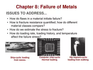
ENS 205 Chapter 8 Failure Analysis and Prevention. What happened ?. Preventing Failure. In service, under loading (mechanical, thermal) How to assure performance, safety and durability? Avoid excess deformation that may deteriorate the functionality

E N D
Preventing Failure In service, under loading (mechanical, thermal) • How to assure performance, safety and durability? • Avoid excess deformation that may deteriorate the functionality • Avoid cracking that may propagate to complete fracture • The study of deformation and fracture in materials the response of materials to mechanical loads or deformation.
Deformation and Failure • Deformation • Time independent • Elastic • Plastic • Time dependent • Creep • Fracture • Static loading • Brittle: rapid run of cracks through a stressed material • Ductile • Environmental (combination of stress and chemical effects) • High-strength steel may crack in the presence of hydrogen gas • Creep rupture (creep deformation proceeding to the point of separation) • Fatigue/cycling loading • High cycle/low cycle • Fatigue crack growth • Corrosion fatigue
Types of Failure • Fracture • Cracking to the extent that component to be separated into pieces • Steps in fracture: • crack formation • crack propagation • Depending on the ability of material to undergo plastic deformation before the fracture two fracture modes can be defined - ductile or brittle • Ductile fracture- most metals (not too cold): • Extensive plastic deformation ahead of crack • Crack is “stable”: resists further extension unless applied stress is increased • Brittle fracture- ceramics, ice, cold metals: • Relatively little plastic deformation • Crack is “unstable”: propagates rapidly without increase in applied stress
Fracture of Materials Crack formation mechanisms Metals typically form cracks by the accumulation of dislocations at a crack nucleation site (grain boundaries, precipitate interface, free surface, etc.) Ceramics, semiconductors, some plastics (hard and brittle, eg., thermosetting plastics) and intermetallic compounds form cracks by planar defects (grain boundaries, two-phase interfaces, etc.) Soft plastics crack by the sliding of the long polymer chairs across each other by breaking the Van der Wall bonds.
Fracture of Materials Fracture can be classified according to the path of crack propagation: • Transgranular – the crack travels directly through the grains of the material (sometimes called cleavage because it occurs along certain crystallographic planes). It can be ductile or brittle. • Intergranular – the crack propagates along grain boundaries. This is primarily brittle fracture. A variety of Loading Conditions can lead to fracture: • Static Overloading (s > syield) and (s > Tensile Strength) • Dynamic Overloading (impacting) • Cyclic loading (fatigue) • Loaded at elevated temperatures (creep) • Loading at cryogenic temperatures (ductile to brittle transition) • Loading in a corrosive environment (stress corrosion)
Brittle vs. Ductile Fracture • Ductile materials - extensive plastic deformation and energy absorption (“toughness”) before fracture • Brittle materials - little plastic deformation and low energy absorption before fracture
Impact Fracture Testing Fracture behavior depends on many external factors: • Strain rate • Temperature • Stress rate Impact testing is used to ascertain the fracture characteristics of materials at a high strain rate and a triaxial stress state. In an impact test, a notched specimen is fractured by an impact blow, and the energy absorbed during the fracture is measured. There are two types of tests – Charpy impact test and Izod impact test.
Impact Test: The Charpy Test The ability of a material to withstand an impact blow is referred to as notch toughness. The energy absorbed is the difference in height between initial and final position of the hammer. The material fractures at the notch and the structure of the cracked surface will help indicate whether it was a brittle or ductile fracture.
Impact Test (Charpy) Data for some of the Alloys In effect, the Charpy test takes the tensile test to completion very rapidly. The impact energy from the Charpy test correlates with the area under the total stress-strain curve (toughness)
Impact Test: The Izod Test Generally used for polymers. Izod test is different from the Charpy test in terms of the configuration of the notched test specimen
Impact Tests: Test conditions • The impact data are sensitive to test conditions. Increasingly sharp notches can give lower impact-energy values due to the stress concentration effect at the notch tip • The FCC alloys→ generally ductile fracture mode • The HCP alloys→ generally brittle fracture mode • Temperature is important • The BCC alloys→ brittle modes at relatively low temperatures and ductile mode at relatively high temperature
Transition Temperatures • As temperature decreases a ductile material can become brittle - ductile-to-brittle transition • The transition temperature is the temp at which a material changes from ductile-to-brittle behavior • Alloying usually increases the ductile-to-brittle transition temperature. FCC metals remain ductile down to very low temperatures. For ceramics, this type of transition occurs at much higher temperatures than for metals.
Ductile to Brittle Transition The results of impact tests are absorbed energy, usually as a function of temperature. The ABSORBED ENERGY vs. TEMPERATURE curves for many materials will show a sharp decrease when the temperature is lowered to some point. This point is called the ductile to brittle transition temperature (relatively narrow temperature range). A typical ductile to brittle transition as a function of temperature. The properties of BCC carbon steel and FCC stainless steel, where the FCC crystal structure typically leads to higher absorbed energies and no transition temperature.
Transition Temperatures • BCC metals have transition temperatures • FCC metals do not • Can use FCC metals at low temperatures (eg Austenitic Stainless Steel)
Brittle Fracture Failure of Liberty ships in WW II - Low-carbon steels were ductile at RT tensile tests, they became brittle when exposed to lower-temperature ocean environmets.The ships were built and used in the Pacific Ocean but when they were employed in the Atlantic Ocean, which is colder, the ship’s material underwent a ductile to brittle transition.
Alloying usually shifts the ductile-to-brittle transition temperature Carbon content increases the brittleness
The fracture surface Ductile → a dimpled texture Brittle → cleavage surface cleavage : The tendency of certain minerals to break along distinct planes in their crystal structures where the bonds are weakest Near the ductile-to-brittle transition temperature, the fracture surface exhibits a mixed texture
Fracture Mechanics: The general analysis of the failure of structural materials with preexisting flaws→ The main outcome of the analysis is fracture toughness
Fracture Mechanics • Fracture strength of a brittle solid is related to the cohesive forces between atoms. • One can estimate that the theoretical cohesive strength of a brittle material should be ~ E/10. But experimental fracture strength is normally E/100 - E/10,000. • This much lower fracture strength is explained by the effect of stress concentration at microscopic flaws. • The applied stress is amplified at the tips of micro-cracks, voids, notches, surface scratches, corners, etc. that are called stress raisers. The magnitude of this amplification depends on micro-crack orientations, geometry and dimensions.
Fracture Mechanics • Cracks or crack-like flaws (surface scratches, voids in welds, delaminations, foreign substances in cast materials…) exist frequently • Commercial aircraft • Ship structures • Bridges • Pressure vessels and piping • Fracture mechanics: a methodology to aid in selecting materials and designing components to minimize the possibility of fracture where cracks are difficult to avoid
The uniform stress field is altered in the vicinity of the hole Stress concentration factor depends of geometry Theoretically, a sharp crack (zero tip radius) causes a severe concentration of stress (infinite stress) Fracture Mechanics One important reason for the big difference in theoretical and experimental values in fracture strength is cracks. • There always exists cracks or flaws in solid materials. Why? • Stress is enlarged at the crack tip (stress raisers).
Cracks as stress raisers • In practice, the theoretically infinite stress relieved by modifying the sharp crack tip • ductile material can accommodate the presence of an initially sharp crack as large plastic deformation in the vicinity of the tip results in blunted crack tip and finite stress values - the plastic zone • Some polymers, a region containing elongated voids develops that contains a fibrous structure bridging the crack faces- craze zone • Brittle materials, a region containing high density of tiny crack • Crack tip experiences intense deformation and finite separation near its tip • High stress is spread over a larger region - redistributed Mechanical Behaviour of Materials, N. E. Dowling
Fracture Toughness What is fracture toughness? Critical value of the stress-intensity factor at a crack tip necessary to produce catastrophic failure under simple uniaxial load. The stress intensity at the crack tip is dependent on both the applied stress and the length of the crack. A new mechanical variable, Stress Intensity Factor, KI, is used to describe the relationship: Where, I→ stands for mode: uniaxial loading C → stands for mode: critical f is a dimensionless constant (related to geometry of specimen and flaw) • is the applied stress a is the crack length or half the length of an internal crack KI is a variable but NOT a materials property KI has unusual unit of Mpa(m)½ or psi(in)½ .
Fracture Toughness Fracture Toughness When the stress intensity, KIis increased to a critical value, KIC , crack propagation will occur, which will lead to fracture. Analogy: A balloon with a small pinhole will catastrophically fails starting from the pinhole location when the pressure has reached a critical value. Where, KIC is a measure of a materials resistance to crack propagation. It is a material property. KIC is dependent on temperature, microstructure, and strain rate. KIC usually increases with a reduction in grain size.
Fracture Toughness How to use KIC ? • Fracture toughness is most useful in mechanical designs involving materials with limited toughness or ductility. • Usually s < syield/n is good enough for ductile materials, which are statically loaded. • Design criterion using KIC : taking into account KIC , which is a material property, the allowable stress (s) and/or the allowable flaw size (a) can be determined. Material Selection: • If the maximum applied stress, smax , and maximum crack length are specified for a certain application, then only the materials with KIC greater than KI can be used:
Highly brittle materials with little or no ability to deform plastically in the vicinity of a crack tip have low KIC values and are susceptible to catastrophic failure. High ductility alloys can undergo significant plastic deformation on both macroscopic and microscopic scale before fracture. Fracture Toughness
Fracture Toughness Allowable stress design (if “a” and KIC are specified by application constraints)
Effects of Cracks on Strength • The value of KIC decreases with increasing strain rate and decreasing temperature • Refining the grain increases KIC • If load is too high the crack may suddenly grow, fracture in brittle manner with little plastic deformation • Stress intensity factor, K: characterizes the severity of the crack situation as affected by crack size, stress, and geometry
Microstructure of Fracture in Metals Most often ductile fracture occurs in a transgranular manner, which means through the grains rather than only along grain boundaries. Brittle fracture is typically intergranular or along the grain boundaries, which is enhanced when impurities collect and weaken the grain boundaries. In a simple tensile test, ductile fracture begins by the nucleation, growth and coalescence of microvoids at the center of a sample (in the necked region). The stress causesseparation of the grain boundaries or the interfaces between the metal and small impurity particles (inclusions or precipitates). As the local stresses increase, the micro-voids grow and coalesce into larger cavities. Eventually the metal-to-metal contact is too small to support the load and fracture occurs.
Microstructure of Fracture in Metals Formation of voids in the necked region during tensile testing, leading to fracture.
Fatigue is the lowering of strength or failure of a material due to repetitive stress, which may be above or below the yield strength. Many engineering materials such as those used in cars, planes, turbine engines, machinery, shoes, etc are subjected constantly to repetitive stresses in the form of tension, compression, bending, vibration, thermal expansion and contraction or other stresses. There are typically three stages to fatigue failure. First a small crack is initiated or nucleates at the surface and can include scratches, pits, sharp corners due to poor design or manufacture, inclusions, grain boundaries or dislocation concentrations. Second the crack gradually propagates as the load continues to cycle. Third a sudden fracture of the material occurs when the remaining cross-section of the material is too small to support the applied load. At a local size scale the stress intensity exceeds the yield strength. For fatigue to occur at least part of the stress in the material has to be tensile. Fatigue is most common in metals and plastics, whereas ceramics fail catastrophically without fatigue because of their low fracture toughness. Fatigue
Fatigue Fatigue failures are often easy to identify. The fracture surface near the origin is usually smooth (Beach mark-crack initiation point). The surface becomes rougher as the crack increases in size. Striations (concentric line patterns): the slow cyclic build up of crack growth from a surface intrusion. Striations are on a much finer scale and show the position of the crack tip after each cycle. Granular portion of the fracture surface: rapid crack propagation at the time of catastrophic failure
Fatigue under cyclic/repeated loading • Cracks generally grow under repeated loading • Trucks passing over bridges, • Sailboat rudders • Bicycle pedals • May result failure or fracture: fatigue fracture • Periodic inspections required for fatigue critical systems • Thermal fatigue: repeated heating and cooling can cause a cyclic stress due to differential thermal expansion and contraction
Fatigue • Repeated, also called cyclic loads resulting in cyclic stresses can lead to microscopic physical damage. • Accumulation of this microscopic damage with continued cycling is possible until it develops into a macroscopic crack such as cracks that may lead to failure • Fatigue: Damage progression to failure due to repeated or cyclic loading at amplitudes considerably lower than tensile or yield strengths of material under a static load • Estimated to causes 90 % of all failures of metallicstructures (bridges, aircraft, machine components, etc.) • Fatigue failure is brittle-like (relatively little plasticdeformation) - even in normallyductile materials. Thussudden and catastrophic!
Fatigue Data The most important fatigue data for engineering designs are the S-N curves, which is the Stress-Number of Cycles curves. In a fatigue test, a specimen is subjected to a cyclic stress of a certain form and amplitude and the number of cycles to failure is determined. The number of cycles, N, to failure is a function of the stress amplitude, S. A plot of S versus N is called the S-N curve.
Definitions and Concepts • Constant amplitude stressing • Mean stress • Stress amplitude (half of the range) variation about the mean • Stress ratio R, Amplitude ratio • Completely reversed stressing, R=-1
Fatigue Failures Types of stresses for fatigue tests include, axial (tension – compression) flexural (bending) torsional (twisting) From these tests the following data is generated. By convention, tensile stresses are positive and compression stresses are negative.