Download
1 / 15
150 likes | 272 Vues
Dive into hands-on electronics with the Heater Circuit Kit! This engaging kit comes with everything you need to build your own heating circuit, including 3.9V batteries, a perf board, ceramic resistors, and all necessary wiring. Follow the comprehensive assembly instructions to connect components and solder your circuit. Learn to check continuity, safely secure connections with electrical tape, and test your circuit's functionality. Ideal for students and DIY enthusiasts, this kit makes learning about circuits practical and fun!

E N D
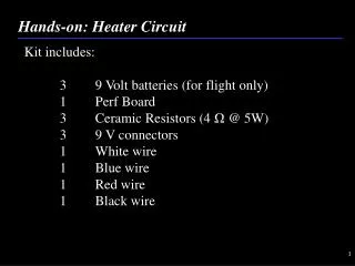
Hands-on: Heater Circuit Kit includes: 3 9 Volt batteries (for flight only) 1 Perf Board 3 Ceramic Resistors (4 Ω @ 5W) 3 9 V connectors 1 White wire 1 Blue wire 1 Red wire 1 Black wire
Hands-on: Heater Circuit 1. Set out kit
Hands-on: Heater Circuit 2. Layout Resistors on PerfBoard Front: Back:
Hands-on: Heater Circuit 3. Fold the leads of two of the resistors and solder them together as shown:
Hands-on: Heater Circuit 4. Clip the leads:
4Ω 4Ω 4Ω Hands-on: Heater Circuit 5. Repeat steps 3 and 4 so the resistors are soldered in series, using the leads of the resistors
Hands-on: Heater Circuit Your circuit should look like this:
Hands-on: Heater Circuit 6. Twist all the Red wires from the 9V connector together and solder them to the single red wire in your kit
Hands-on: Heater Circuit 7. Twist all the Black wires from the 9V connector together and solder them to the single black wire
Hands-on: Heater Circuit 8. Check continuity for all “-” and “+” terminals to each other
Hands-on: Heater Circuit 9. Check continuity for all “+” terminals of the battery with the end of the single RED wire 10. Check continuity for all “-” terminals of the battery with the end of the single BLACK wire
Hands-on: Heater Circuit 11. Put electrical tape on solder joints
4Ω 4Ω 4Ω Hands-on: Heater Circuit 12. Solder the single RED wire from 9V connector to one end of the resistor string and the WHITE wire to the other end of the resistor string *Green boxes are battery connectors
4Ω 4Ω 4Ω Hands-on: Heater Circuit 13. Solder the switch in between the black wire and the white wire
4Ω 4Ω 4Ω Hands-on: Heater Circuit 14. Test your finished Heater by turning on the switch and putting your finger on the resistors – if they get warm, you’re done. If they don’t, check continuity at the following points: