Mutual Inductance
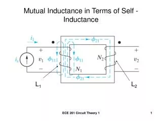
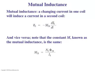
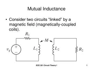
Mutual Inductance. Consider two circuits “linked” by a magnetic field (magnetically-coupled coils). “Self-Inductances” are L 1 and L 2 . The “Mutual” Inductance is M. The voltage induced in one circuit is related to the time-varying current in the other circuit. Analysis.

Mutual Inductance
E N D
Presentation Transcript
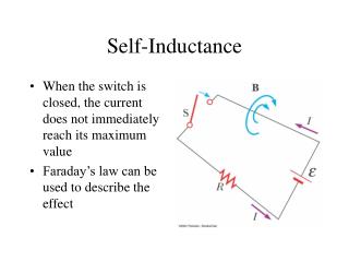
Mutual Inductance • Consider two circuits “linked” by a magnetic field (magnetically-coupled coils). ECE 201 Circuit Theory I
“Self-Inductances” are L1 and L2. The “Mutual” Inductance is M. The voltage induced in one circuit is related to the time-varying current in the other circuit. ECE 201 Circuit Theory I
Analysis • Easiest with mesh-current method. ECE 201 Circuit Theory I
Write the circuit equations in terms of the coil currents. Arbitrarily assign the current directions. There will be two voltages across each coil, the “self-induced” voltage, L(di/dt), and a “mutually induced” voltage, M(di/dt). ECE 201 Circuit Theory I
Determination of Voltage Polarities • “Dot convention” • Dots indicate the direction in which the coils are wound. ECE 201 Circuit Theory I
The Rule for using the Dot Convention • When the reference direction for a current enters the dotted terminal of a coil, the reference polarity of the voltage that it induces in the other coil is positive at its dotted terminal. ECE 201 Circuit Theory I
Alternate Rule for the Dot Convention • When the reference direction for a current leaves the dotted terminal of a coil, the reference polarity of the voltage that it induces in the other coil is negative at its dotted terminal. ECE 201 Circuit Theory I
For this Example • The voltage induced in coil 1 by the current in coil 2 is negative at the dotted terminal of coil 1, and is a voltage rise with respect to current i1. ECE 201 Circuit Theory I
For this Example • The voltage induced in coil 2 by the current in coil 1 is positive at the dotted terminal of coil 2, and is a voltage rise with respect to current i2. ECE 201 Circuit Theory I
Write the Mesh Equations ECE 201 Circuit Theory I
Example 6.6, page 206 • Write a set of mesh equations that describe the circuit shown in terms of i1 and i2. ECE 201 Circuit Theory I