Mine Drop Experiment (MIDEX)
Mine Drop Experiment (MIDEX). Anthony Gilles Naval Postgraduate School, Monterey, CA 93943. Mine Drop Experiment (MIDEX). Republic of Korea minesweeper YMS-516 is blown up by a magnetic mine, during sweeping operations west of Kalma Pando, Wonsan

Mine Drop Experiment (MIDEX)
E N D
Presentation Transcript
Mine Drop Experiment(MIDEX) Anthony Gilles Naval Postgraduate School, Monterey, CA 93943
Mine Drop Experiment(MIDEX) Republic of Korea minesweeper YMS-516 is blown up by a magnetic mine, during sweeping operations west of Kalma Pando, Wonsan harbor, on 18 October 1950.From http://www.history.navy.mil/photos/events/kowar/50-unof/wonsan.htm
Acknowledgements • Chenwu Fan • Marla Stone • ET1 Adam Dummer • George Jaksha • Prof. Chu
Overview • Mine Warfare Overview • Important Environmental Parameters for MCM Operations • Impact Burial Prediction Model • Mine Drop Experiment Overview • Hydrodynamic Theory • Data Analysis • Conclusion • Questions
A Shift in Operational Focus • Breakdown of Soviet Union Forced Change in U.S. Navy Mission Requirements. • Primary Guiding Documents: … From the Sea, Forward … From the Sea, Operational Maneuver from the Sea. • Shift in Mission Focus from Open Ocean to the Littoral. • Greatest Threat to U.S. Forces Operating in the Littoral: the Naval Mine.
Naval Mine Characteristics • Characterized by: • Method of Delivery: Air, Surface or Subsurface. • Position in Water Column: Bottom, Moored or Floating. • Method of Actuation: Magnetic and/or Acoustic Influence, • Pressure, Controlled or Contact. • Composed of metal or reinforced fiberglass. • Shapes are Typically Cylindrical but Truncated • Cone (Manta) and Wedge (Rockan) shaped mines exist.
Naval Mine Threat Inexpensive Force Multiplier Widely Available Roberts (FFG-58), Tripoli (LPH-10), Princeton (CG-59) Damages $125 Million; Mines Cost $30K • Over 50 Countries • (40% Increase in 10 Yrs) • Over 300 Types • (75% Increase in 10 Yrs) • 32 Countries Produce • (60% Increase in 10 Yrs) • 24 Countries Export • (60% Increase in 10 Yrs) Numerous Types WWII Vintage to Advanced Technologies (Multiple Sensors, Ship Count Routines, Anechoic Coatings Non-Ferrous Materials)
Important Environmental Parameters for MCM Operations • Water Properties • Weather • Beach Characteristics • Tides and Currents • Biologics • Magnetic Conditions • Bathymetry (Bottom Type)
Impact Burial • Mine Impacting Bottom will Experience a Certain Degree of “Impact Burial (IB)”. - Highest Degree of IB in Marine Clay and Mud. - IB Depends on Sediment Properties, Object’s Impact Orientation, Shape and Velocity. • MCM Doctrine Provides only a Rough Estimate of IB.
Development of Navy’s Impact Burial Prediction Model (IBPM) • IBPM was designed to calculate mine trajectories for air, water and sediment phases. • Arnone & Bowen Model (1980) – Without Rotation. • Improved IBPM (Satkowiak, 1987-88) – With Rotation. • Final Improvements made by Hurst (1992): - More Accurately Calculates Fluid Drag and Air-Sea and Sea-Sediment Interface Forces. - Treats Sediment as Multi-Layered.
Impact 25 • Main Limitations: 1. Model assumes mine body is of uniform density, thus center of buoyancy coincides with center of mass. 2. Model numerically integrates momentum balance equations only. Does not consider moment balance equations. • If a mine’s water phase trajectory is not accurately modeled, then IB predictions will be wrong. • Recent sensitivity studies by (Chu et al., 1999, 2000, Taber 1999, Smith 2000) have only focused on sediment phase calculations.
MIDEX • MIDEX designed to examine the uniform density assumption of IMPACT 25, namely what effect a varying center of mass will have on a mine shape’s water phase trajectory. • Controlled Parameters: 1. Drop Angles: 15º, 30º, 45º, 60º, 75º. 2. Center of Mass Position. 3. L/D ratio (constant). 4. Vinit (to some extent). • Conducted several tests for each drop angle, center of mass position and initial velocity.
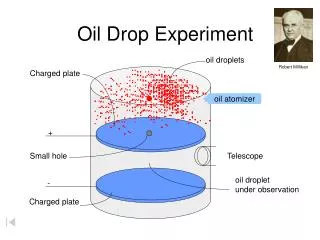
To Universal Counter Light Sensor Drop Angle Control Device Mine Injector Mine Shapes: Length: 15, 12, 9 cm Diameter: 4 cm
X -Z Mine Attitude (Psi) Coordinate System
Center of Mass Defined COM position as: 2 or -2: Farthest from volumetric center 1or -1 0: Coincides with volumetric center
Hydrodynamic Theory 1. Momentum Balance * Denotes dimensional variables V* Velocity W* gravity Fb* buoyancy force Fd* drag force 2. Moment of Momentum Balance M* resultant moment • Solid Body Falling Through Fluid Should • Obey 2 Physical Principles:
Hydrodynamic Theory • Considering both momentum and moment of momentum balance yields 9 governing equations that describe the mine’s water phase trajectory.
Improved IBPM with rotation but without Moment Equation Arnone-Bowen IBPM Without Moment Equation Hydrodynamic Theory
Hydrodynamic Theory • By considering both equations mine will exhibit a • spiral fall pattern.
Data Analysis • Video converted to digital format. • Digital video from each camera analyzed frame by frame (30Hz) using video editing program. • Mine’s top and bottom position determined using background x-z and y-z grids. Positions manually entered into MATLAB for storage and later processing. • Analyzed 2-D data to obtain mine’s x,y and z center positions, attitude (angle with respect to z axis) and u,v, and w components.
Non-dimensional Conversions • In order to generalize results, data was converted • to non-dimensional numbers.
Sources of Error • Grid plane behind mine trajectory plane. Results in mine appearing larger than normal. • Position data affected by parallax distortion and binocular disparity. • Air cavity affects on mine motion not considered in calculations. • Camera plane not parallel to x-y plane due to pool slope.
Impact Point (All Drop Angles) COM Position 2 1
COM Position 0 -1 -2
Impact Angle Frequency of Occurrence COM 2 COM 1 COM 0 COM -2 COM -1
Trajectory Patterns • Straight • Slant • Spiral • Flip • Flat • See Saw • Combination
Multiple Linear Regression • General Multiple Linear Regression Equation: • Used least squares solution to determine correlation coefficients. • Input: cos(drop angle);L/D;Vind; COMnd • Output: (xm, ym, zm, Psi, u, v, w)
Multiple Regression Results • Most important parameter for impact prediction is Psi (impact angle).
Conclusion • COM position is the most influential parameter for predicting a mine’s impact position and angle. • Final velocities were lowest for COM 0 cases due to the increased effect of hydrodynamic drag. • Trajectories became more complex as L/D decreased (9 cm mine rotated about z-axis). • Observed trajectory patterns were more complex than those assumed by IMPACT 25. Accurate representation of a mine’s water phase motion requires both momentum and moment of momentum equations.