Download
1 / 61
1.05k likes | 2.72k Vues
THEORY OF METAL MACHINING. Machining variables. There are two kinds of machining variables : Independent variables Dependent variables. In cutting process, the major independent variables , that is, the variables that we can change and control directly, are :

E N D
Machining variables • There are two kinds of machining variables: • Independent variables • Dependent variables. • In cutting process, the major independent variables, that is, the variables that we can change and control directly, are : • Type of cutting tool and its condition (the tool material) • Tool shape and its sharpness • work part material and its conditions • Cutting conditions (speed, feed and depth of cut) • Type of cutting fluids • Characteristics of the machine tool, particularly its stiffness and damping • Tool holders and fixturing device
Machining variables • The dependent variables, which are the variables that are influenced by changes in the independent variables, are: • Type of chip produced • Force required and energy dissipated in the cutting process • The temperature rise in the work piece, the chip and the tool • Surface finish and integrity of the work piece after it is machined • It is important to study the complex interrelationships among these variables. Why???????
Machining variables • If the surface finish of workpiece being cut is poor and unacceptable, we need to know which of the pervious independent variables do we modify? • If the workpiece becomes too hot, thus affecting its properties, what modifications should be made? • If the cutting tool wears rapidly and becomes dull, what should we do? Do we change the cutting speed, the depth of cut, the tool material itself, or some other variables? • If the dimensional tolerance of the machined workpiece is over the specified limits, what modification should be made? • If the cutting tool begins to vibrate and chatter, thus affecting surface finish, so what should be done to eliminate this problem?
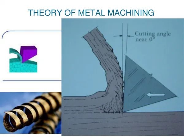
Mechanism of chip formation • Machining processes remove material from the workpiece surface by producing chips as shown the below figure.
Mechanism of chip formation • The basic mechanics of chip formation, which is essentially the same for all cutting operations is represented by two-dimensional model (a) orthogonal cutting with well-defined shear plane also known as merchant (b) orthogonal cutting without a well-defined shear plane
Mechanism of chip formation • In this model • A tool moves along the workpiece at a certain velocity (cutting speed), V, and a depth of cut, to ( in orthogonal model) • A chip is produced just a head of the tool by shearing the material continuously along the shear plane
Mechanism of chip formation • In this model, which is known a orthogonal cutting [meaning that the cutting edge of the tool is perpendicular (orthogonal) to the cutting direction] • The tool has • a rake angle (α) • And a relief or clearance angle • The sum of the rake, relief and included angles of the tool is 1.57 rad (90o)
Mechanism of chip formation • Microscopic examinations reveal that chips are produced by shearing mechanism as shown. • Shearing take place along a shear plane, which make an angle Ф, called shear angle, with the surface of the workpiece. • Below the shear plane, the work piece is undeformed and above the shear plane, a chip is already formed and is moving up the face of the tool as cutting progress. • Because of the relative movement, there is a friction between the chip and rake face of the tool
Cutting ratio • Note that the thickness of the chip, tc, can be determined if to,α, and Ф are known. • The ratio of tototcis known as the cutting ratio, r, which can be expressed as: • where: r = chip thickness ratio; to = thickness of the chip prior to chip formation; tc = chip thickness after separation • Chip thickness after cut always greater than before, so chip ratio always less than 1.0
Cutting ratio • Cutting relation Can be derived using trigonometricrelations here. • By rearranging the above equation based on the geometric parameters of the orthogonal model, and using the trigonometric identity cos(φ - α)= cos φ cos α + sin φ sin αthe shear plane angle can be determined as: r= chip ratio, = rake angle Ф =Shear angle: where
Shear Strain in chip On the base of the figure below, the shear strain, that the material undergoes during cutting can be expressed as in the followingbequation:
Shear Strain in chip • Shear strain in machining can be computed from the following equation, based on the preceding parallel plate model: • = tan( - ) + cot • where = shear strain, = shear plane angle, and = rake angle of cutting tool. • Note from this equation that high shear strains are associated with low shear angles and rake angles. • Shear strain of 5 or higher have been observed in actual cutting operations. Thus, compared with forming and shaping processes, the material undergoes greater deformation as can be seen the next table
Velocity • Since the chip thickness, tc, is greater than the undeformed chip thickness, to, the velocity of the chip, Vc, must be lower than the cutting speed, V. since mass continuity has to be determined, we have • From the figure, note that the undeformed chip thickness, to, and the depth of cut are the same parameter for the orthogonal cutting; this is not true for other operations.
Shear-strain rate • The shear-stain rate is the ratio of Vs to thickness a of the sheared element (shear zone) a • The magnitude of the shear-strain rate is very high. Why??????? • Because of the very high deformation that occur at small area. • Because the magnitude of a is on the order of 10-2 to 10-3 mm. this range indicates that, even at low cutting speed ( shearing speed), the shear-strain rate is very high, on the order of 103/s to 106/s
Chip morphology • The type of chips produced (chip morphology) significantly influences surface finish and integrity of the machined part. • The chip has two faces: • One surface has been in contact with the rake face of the tool • The other surface is from the original surface of the workpiece.
Chip morphology • The tool side of the chip surface is shiny or burnished, caused by the rubbing of the chip as it climbs up to the tool surface. • The other surface of the chip has not come into contact with any solid body. So it has a jagged, steplike appearance, which is due to the shearing mechanism of chip formation.
Four Basic Types of Chip in Machining • Discontinuous chip • Continuous chip • Continuous chip with Built-up Edge (BUE) • Serrated chip
Discontinuous Chip • Discontinues chips consist of segments that may be either firmly or loosely attached to each other.
Discontinuous Chip • These chips usually form under the conditions: • The workpiece material is brittle, [because brittle material can not undergo the high shear strains involved in cutting]. • The workpiece material contains hard inclusions and impurities.Impurities and hard particles act as sites for cracks, thereby, producing discontinuous chips. As expected, a large depth of cut increases the probability of such Chip • The depth of cut ( undeformed chip thickness) is larger than rake angle. • There is a lake of an effective cutting fluid. • The cutting speed is very low • The machine tool has low stiffness and poor damping of the cutting tool.
Discontinuous Chip • Because of the discontinuous nature of chip formation, forces continually vary during cutting. Consequently, the stiffness of cutting tool holder, the workpiece holding devices, and the machine tool is important in cutting with discontinuous chips as well as serrated-chip formation. If not sufficiently stiff, the machine tool may begin to vibrate and chatter. This effect, in turn, adversely affects the surface finish and dimensional accuracy of the machine part and may even cause damage or excessive wear of the cutting tool, as well as the machine tool itself.
Continuous Chip • Continuous chips are typically formed in Ductile work materials (e.g., low carbon steel) at: • High cutting speed and/or high rake angles • Small feeds and depths • Sharp cutting edge on the tool • Low tool-chip friction • The deformation of the material takes place along a very narrow zone, called primary shear zone. Such chips also may develop a secondary shear zone at tool-chip interface, caused by friction. The secondary zone becomes thicker as tool-chip friction increases
Continuous Chip • CONTINOUS chips generally produce a good surface finish, but they are not always desirable. Why ????? • Particularly, in computer-controlled machined tools, because they tend to get tangled around the tool, and the operation has to stopped to clear away the chips. • This problem can easily be solved with chip breakers features on cutting tool. • Because of the shear strain that the chip is subjected to. The chip will be in a state of strain hardening. As a result of that the chip becomes harder and stronger, and less ductile, than the original workpiece material. • The increase in the hardness and strength of the chip depends on the magnitude of the shear strain. As the rake angle decreases, the shear strain increases, and thus the chip becomes stronger and harder
Continuous Chip • In continuous chips, deformation may also take place along a wide primary shear zone with curved boundaries ( figure b). • Note that the lower boundary of the zone is below the machined surface, which subjects the machined surface to distortion and possible damage • This situation occurs particularly often in machining soft metalsat low cutting speeds and low rake angles; it can produce a poor surface finish and also induce residual surface stresses, which may be detrimental to the properties of the machined part
Continuous with BUE • A built-up edge (BUE) chip may form with a ductile material at the tip of the cutting tool. • It consists of layers of material from the work piece that are gradually deposited on the tool (hence the term built-up). • As it becomes larger, the BUE becomes unstable and eventually breaks up. • The upper portion of the BUE is carried a way on the tool side of the chip, and the lower portion is deposited randomly on the machine surface. • The process of BUE formation and breakup is repeated continuously during the cutting operation.
Continuous with BUE • The built-up edge is one of the important factors that adversely affects surface finish and integrity of the machined part. In which the BUE changes the geometry of cutting operation. How???? • Large tip radius of the BUE will produce a rough surface finish, because of work hardening and deposition of successive layers of material, BUE hardness increase significantly. • Although BUE is generally undesirable, but a thin stable BUE (dose not break) is generally regarded as desirable because it protect the tool surface Surface finish in turning steel with built-up edge Surface finish in face milling
Continuous with BUE • Although the exact mechanism of BUE formation is not clearly understood, investigations have identified the factors that contribute to the formation of BUE: • Adhesion of the workpiece material to rake face of the tool, the strength of this bond depending on the affinity of the workpiece and tool materials [ ceramic cutting tools, for example, have much lower affinity to form BUEs than do tool steels]. • Growth of the successive layers of adhered metal on the tool. • Tendency of workpiece material for strain hardening; the higher the strain hardening exponent, n, the higher is the probability for BUE formation. [ the separation of more hardness material from the less one] • The Buit-up edge decreases or is eliminated as : • The cutting speed, v, increases • The depth of cut, to,decreases • The rake angle, α, increases • Tip radius of the tool decreases
Serrated Chip • Serrated chip, also called segmented or Semicontinuous or nonhomogeneous chips. • They are Semicontinuous chips with zones of low shear and high shear strain. • The chips have the appearance of saw teeth (hence the term serrated) • Metals, such as titanium, with low thermal conductivity and strength decreases sharply with temperature exhibit this behavior.
Forces Acting on Chip (all the forces) • Analysis – Forces in cutting: • Forces acting on the chip: • Two types of forces • Forces can not be measured • Forces can be measured using dynometer
Forces Acting on Chip • Analysis – Forces in cutting: • Forces acting on the chip: µ ) • F, N, Fs, and Fn cannot be directly measured • The friction force, F, along the tool-chip interface • The normal force, N, which is perpendicular to the interface • These two forces produce the resultant force, R. • The shear force, Fs, along the shear plane • Normal force to shear, Fn, which is perpendicular to shear plane • These two forcese produce the resultant force, R’.
Resultant Forces • Vector addition of F and N = resultant R • Vector addition of Fs and Fn = resultant R' • Forces acting on the chip must be in balance: • R' must be equal in magnitude to R • R’ must be opposite in direction to R • R’ must be collinear with R
Forces Acting on Chip • Analysis – Forces in cutting: • Forces acting on the chip: • The cutting force, Fc, acts in the direction of the cutting speed, v, and supply the energy required for the machining operation. • The thrust force (feed force), Ft, acts in the direction normal to cutting velocity, that is perpendicular to the workpiece. • These two forces produce the resultant force, R’’ . • Forces acting on the tool that can be measured: • Cutting force Fc and Thrust force Ft
Need of analysis of forces • Analysis of cutting forces is helpful as : • Determination of power consumption [ estimation of cutting power consumption, which enables selection of the power source(s)(motor selection) during design of machine tool]. • Knowing cutting forces is helpful in designing the machine in regard the stiffness and damping • To obtain maximum productivity[if you know forces acting on cutting tool we can easily predict life of the tool so we can obtain balance between life of the tool and rate of cutting in order to obtain maximum productivity].
Merchant’s circle Diagram Force Diagram
Merchant’s circle Diagram Force Diagram β β
How to measure Ф (dependent) variable, since α is independent variables????? Merchant’s circle Diagram Force Diagram • Forces acting on the tool that can not be measured: • Forces acting on the tool that can be measured • How theses forcescan be • measured?????
Forces in Metal Cutting • Equations can be derived to relate the forces that cannot be measured to the forces that can be measured: F = Fc sin + Ft cos N = Fc cos ‑ Ft sin Fs = Fc cos ‑ Ft sin Fn = Fc sin + Ft cos • Based on these calculated force, shear stress and coefficient of friction can be determined
Coefficient of Friction • Friction angle: • Coefficient of friction between tool and chip: • Coefficient of friction related to friction angle as follows:
Coefficient of Friction • In metal cutting, µ generally ranges from about 0.5 to 2, thus indicating that the chip encounters considerable frictional resistance while climbing up the rake face of the tool
Shear Stress • The forces in the shear plane can be resolved into shear and normal forces • The area, Ao, of the shear plane is: Ʈ = • Shear stress acting along the shear plane: Shear stress = shear strength of work material during cutting • And the normal stress, σ, is:
Shear angle relation shipsHow to measure Ф??? • The Merchant Equation • This theory based on the assumption that • The shear angle adjusts itself so that the cutting force is a minimum [the minimum cutting force required when the shear plane takes place to have minimum cutting energy]. • Of all the possible angles at which shear deformation can occur, the work material will select a shear plane angle that minimizes energy, given by: In degree In rad
What the Merchant Equation Tells Us • Lower shear plane angle • As the rank angle decreases (the friction at the tool-chip interface increases and thusβincreases ) the shear angle decreases, and thus the chip becomes thicker. • This result is expected, because decreasing α and increasing βtend to present greater resistance to chip as it moves up the rake face of the tool, thus making the chip thicker, indicating a lower shear angle