THROUGHPUT
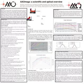
Red Camera. Dichroic. Collimator. Point Spread Function in pixels for MOS and IFU use and for expected aberrations. Slit. Red Grating. Blue Grating. Blue Camera. SUMMARY

THROUGHPUT
E N D
Presentation Transcript
Red Camera Dichroic Collimator Point Spread Function in pixels for MOS and IFU use and for expected aberrations Slit Red Grating Blue Grating Blue Camera SUMMARY AAOmega is a new spectrograph for the existing 2dF fibre-positioning system on the Anglo-Australian Telescope. It is a bench-mounted, dual-beamed, articulating, all-Schmidt design, using Volume Phase Holographic gratings. The wavelength range is 370-950nm, with spectral resolutions from 1400-10000. The design is extremely simple, but the optical performance is excellent. Throughput, spectral coverage, and maximum resolution are all more than doubled compared with the existing 2dF spectrographs, and stability is increased by orders of magnitude. These features allow entirely new classes of observation to be undertaken, as well as greatly improving existing ones. AAOmega is scheduled for delivery and commissioning in 2005B. THROUGHPUT The efficiency of AAOmega will be at least twice as good than 2dF in all configurations, and much better than this at high dispersion and in the far red. The overall efficiency of reflective and transmissive designs were compared at concept design stage and found to be almost identical; however the reflective design allowed faster cameras and avoided the use of exotic materials and deep aspherics. The peak overall throughput (atmosphere, telescope, seeing losses, fibres, spectrograph, gratings, detectors) in low dispersion use is 17% and 22% in blue and red arms respectively. AAOmega: a scientific and optical overviewWill Saunders1 (will@aaoepp.aao.gov.au), Terry Bridges2, Peter Gillingham1, Roger Haynes1, Greg A. Smith1, Dennis Whittard1, Vlad Churilov1, Allan Lankshear1, Scott Croom1, Damien Jones3 and Chris Boshuizen41. Anglo-Australian Observatory, Epping, NSW Australia. 2. Department of Physics, Queen's University, Kingston, Ontario, Canada. 3. Prime Optics, Eumundi, Queensland, Australia. 4. University of Sydney, NSW, Australia. • INTRODUCTION • The original 2dF spectrographs are limited in detector area (1Kx1K detectors), resolution (R<4000), efficiency (5-8%) and stability. In 2000 we started investigating articulating VPH-based alternatives; the original concept was for a pair of all-transmissive spectrographs; but the final adopted design was for a single, dual-beamed, all-Schmidt spectrograph. • SCIENCE DRIVERS • AAOmega will offer a unique combination of field-of-view, fibre numbers and spectral capability. The key science drivers are • ‘Galactic Archaeology’ - the characterisation of the chemical and dynamical structure and history of our Galaxy; • characterising galaxy formation and evolution, through high quality spectra of large numbers of 2dFGS-type galaxies; • characterising the stellar populations of Local Group and other nearby galaxies; • finding the equation of state of the Universe through deeper and larger redshift surveys. • The key instrumental demands of these projects are: • Many projects demand sky subtraction at the 1% level. • Some projects demand 0.1% sky subtraction, only possible with differential measurements involving Nod&Shuffle observations. • Many projects demand high dispersion (R~10000). • Many projects require velocity precision (and hence wavelength stability, calibration accuracy and PSF uniformity) of 1/10 pixel. • Nearly all projects require excellent efficiency. • DESIGN OVERVIEW • The principal AAOmega optical design considerations were as follows: • To use VPH gratings, with their excellent efficiency and flexibility • To accommodate and fully resolve the 392 2dF science fibres. • To maximise the number of spectroscopic resolution elements. • To have excellent optical performance for 370nm-950nm. • To allow use at R=1500-10,000 at any wavelength. • To have spectral stability better than 1/20 pixel over 4 hours. • To minimise scattered light and ghosting. • To be highly efficient. • To use as few and as simple optical components as possible. • To have uniform and well-sampled PSF.. • To allow use with the existing SPIRAL Integral-Field Unit (IFU) front end. • To do all the above within the limited budget and with minimal risk. • In order of the light path, there is • 35m of 140um Polymicro FBP fibre from the existing 2dF top end down to the existing coude west room, where the spectrograph will be situated. • The 392 fibres form a 145mm curved slit • There is a Schmidt f/3.15 collimator with a field lens, spherical mirror, and singlet correctors in each arm below a dichroic beam-splitter acting at 570nm. • There is a VPH grating in each arm; grating angles can be 0º-47º. • Each arm has an f/1.3 Schmidt camera, with camera angles variable from 0º-94º. • Each camera has a doublet corrector lens, a spherical mirror and a plano-spherical field-flattening lens. The corrector also acts as dewar window. • The detectors are E2V 44-82 2k x 4k CCDs with 15micron pixels, back-illuminated in the blue arm and deep-depletion in the red. The short direction is spectral; this is well matched to the angular bandwidth of VPH gratings, and allows nod&shuffling. • The beamsize is 190mm, determined by the competing considerations of obstruction losses and maximum spectral resolution, versus the availability and cost of optics. • The collimator and cameras each have just 4 optical elements for each beam, including just one precision aspheric surface. GRATING SET The VPH grating set allows use at resolutions R~1400, 3500, 8500 over the wavelength range 370nm-950nm. There is an additional ‘Dickson’ grating3, allowing R~11000 over a narrow wavelength range centred on the Calcium Triplet. At a particular grating angle, the bandwidths of VPH gratings are well matched to the spectral coverage in each arm. However, the grating angle can be varied to alter the blaze characteristics. The gratings are manufactured by Ralcon Development Labs of Paradise, Utah. Substrates are Starphire glass for blue gratings, and B270 for red. Peak efficiencies are 80-90%, and all gratings are pre- or post-polished to give transmitted wavefronts better than ½ wave. OPTICAL ABERRATIONS AND POINT SPREAD FUNCTION The predicted optical performance is typically 5μm rms at all wavelengths and configurations, with worst performance 7.8μm rms. These aberrations actually reduce the FWHM of the projected fibre image, from 3.4 to 3.2 pixels. The PSF is at most 7 pixels across, and there are 10 pixels/fibre, so the fibres are completely resolved and cross-talk should be negligible. SCATTERED LIGHT AND GHOSTING Scattered light is a major problem for fibre-fed spectrographs, limiting the dynamic range and also the precision of sky subtraction and equivalent width determinations. The scattered light properties for AAOmega have been very thoroughly investigated, modelling the non-optical surfaces in detail and using the Harvey formulism to estimate surface-scattered light. The estimated combined total scattered light is ~3% at 400nm. Ghosting has also been thoroughly investigated. The worst ghosts found in an analysis of all ghost paths (other than the Littrow ghost described above) have an intensity <10-4. NOD AND SHUFFLE AND SKY-SUBTRACTION Most observations of faint objects are sky-limited. For fibre-based systems, sky subtraction has traditionally been poor. The most efficient (in terms of S/N) method of sky subtraction is with dedicated sky fibres. The errors in this are caused by variable and/or poorly sampled PSF and poor wavelength calibration. AAOmega will have stable PSF and excellent calibration; a sky subtraction error of 1% is anticipated, several times better than 2dF. AAOmega will allow Nod and Shuffle observations, where the telescope is nodded to and from adjacent sky, at the same time as the spectra are charge-shuffled on the detector to and from otherwise unused areas of the detector. Object and sky observations are interleaved on a time-scale of a minute or so. Sky subtraction is much more accurate than traditional offset sky observations, and is at least an order of magnitude more accurate (for 2dF) than sky subtraction with dedicated sky fibres, with accuracies better than 0.1% achieved. This is less than the Poisson noise even for many-hour observations. However, only 200 fibres can be used in this mode. There is also a commitment to implement mini-shuffling, where spectra are shuffled by 4-5 pixels, to give partially resolved, overlapping pairs of object/sky spectra, whose relative strengths can be accurately determined and which are fully resolved from adjacent pairs. Sky subtraction will be intermediate in accuracy between dedicated sky fibres and ‘classic’ N&S; tests of 2dF suggest an accuracy of ~0.3% can be readily achieved, with all fibres being utilised. VPH LITTROW GHOST The first actually delivered VPH gratings from Ralcon, for the 6dF spectrograph on the UK Schmidt, all showed a significant ghost of 0th-order undispersed light, across the chip, at a level 1-2x10⁻⁴ of all imaged dispersed light, with an intensity of several %. The cause of this ghost was eventually tracked down, to be light reflected from the detector, recollimated by the camera, reflected in –1st order by the grating to form an undispersed beam, and re-imaged by the camera onto the detector. This ghosting is intrinsic to all transmission gratings used at Littrow. The ghost can be moved off the detector by altering the grating angle, but this affects the efficiency characteristics of the grating. A better solution is to break the symmetry of the gratings by slanting the fringes within the grating and altering the grating angle so that the reflections within the DCG are symmetric at the blaze wavelength, while the ghost is thrown off the detector.