Logic Design LAB 4
Logic Design LAB 4. 授課老師:伍紹勳 課程助教:邱麟凱、江長庭. BCD Adder. Outlines Requirement Binary and Decimal LAB 4-bit binary full adder Combinational logic of BCD decoder BCD Adder BCD-to-7-Segment Decoders 7-Segment LED. Requirement.

Logic Design LAB 4
E N D
Presentation Transcript
Logic Design LAB 4 授課老師:伍紹勳課程助教:邱麟凱、江長庭
BCD Adder • Outlines • Requirement • Binary and Decimal • LAB • 4-bit binary full adder • Combinational logic of BCD decoder • BCD Adder • BCD-to-7-Segment Decoders • 7-Segment LED
Requirement • IC:7408 x 1、7432 x 1、7483 x 2、7447(DCBA) x 1、LED x 1、7-Segment LED x 1
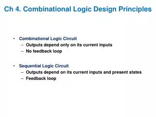
Binary and Decimal • Binary • 4-bit binary digits can represent 16 different numbers (0~15) • Easy to compute in digital circuit • Binary-Coded Decimal(BCD) • A decimal digit can represent10 different numbers (0~9) • Using 4-bit binary digits to represent a decimal digit • Familiar to most people
LAB BCD Adder BCD-to-7-Segment Decoders 4-bit Binary Full Adder Combinational logic
4-bit Binary Full Adder • 74LS83
Combinational logic of BCD decoder • Input 0≦A, B ≦9→ Output 0≦A+B ≦18 • If A+B = 0~9 • Output Carry = 0,Sum = A+B • If A+B = 10~18 • Output Carry = 1, Sum = A+B+6
Combinational logic of BCD decoder • ex: 7+8=15 BCD : 0 1 1 1 +1 0 0 0 1 1 1 1 +0 1 1 0 1 0 1 0 1 >9 => add 6
Binary Sum BCD Sum K T8 T4 T2 T1C S8 S4 S2 S1 0 0 0 0 0 0 0 0 0 0 0 0 1 0 0 0 0 1 0 0 0 0 1 1 2 0 0 0 1 0 0 0 0 1 0 2 3 0 0 0 1 1 0 0 0 1 1 3 4 0 0 1 0 0 0 0 1 0 0 4 5 0 0 1 0 1 0 0 1 0 1 5 6 0 0 1 1 0 0 0 1 1 0 6 7 0 0 1 1 1 0 0 1 1 1 7 8 0 1 0 0 0 0 1 0 0 0 8 9 0 1 0 0 1 0 1 0 0 1 9 A 0 1 0 1 0 1 0 0 0 0 10 B 0 1 0 1 1 1 0 0 0 1 11 C 0 1 1 0 0 1 0 0 1 0 12 D 0 1 1 0 1 1 0 0 1 1 13 E 0 1 1 1 0 1 0 1 0 0 14 F 0 1 1 1 1 1 0 1 0 1 15 10 1 0 0 0 0 1 0 1 1 0 16 11 1 0 0 0 1 1 0 1 1 1 17 12 1 0 0 1 0 1 1 0 0 0 18 13 1 0 0 1 1 1 1 0 0 1 19 T2T1 00 01 11 10 00 01 11 1 1 1 1 10 1 1 T8T4 When to add 6? 1) T8 T4 T2 T1 > 9 T8T4 + T8T2 2) Carry is 1 F = T8T4 + T8T2 + K
BCD Adder T8T4 + T8T2 + K Add 6 or not
BCD-to-7-Segment Decoders • 74LS47 Don’t care
a b f g e c dp d 7-Segment LED • Type “common anodes” seven-segment LED • Common anode pin ‘A’ and ‘k’ connect toVCC • LED illuminate when it’s input pin is low • Reference • http://zh.wikipedia.org/wiki/%E4%B8%83%E5%8A%83%E7%AE%A1
7-Segment LED 330Ω(橘橘棕)
Input T8T4 + T8T2 + K Add 6 or not A,k connect to +5V and dp don’t care Sum Carry ( LED )