Introduction to Machine Vision Systems
Introduction to Machine Vision Systems. Professor Nicola Ferrier Room 3128, ECB 265-8793 ferrier@engr.wisc.edu. Machine Vision. To become familiar with technologies used for machine vision as a sensor for robots.

Introduction to Machine Vision Systems
E N D
Presentation Transcript
Introduction toMachine Vision Systems Professor Nicola Ferrier Room 3128, ECB 265-8793 ferrier@engr.wisc.edu
Machine Vision • To become familiar with technologies used for machine vision as a sensor for robots. • Camera and lighting technology (obtaining a digital representation of an image) • Software (computational techniques to process or modify the image data) • Analysis/decisions: using the results of the processing in robot control • Additional material in CS766, ECE 533, ME 739
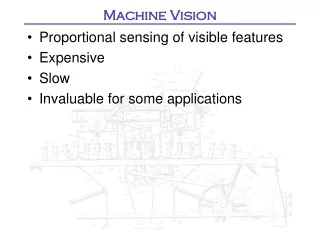
Machine Vision in Automation • Use a camera to inspect parts to: • Guide a robot or control automated equipment • Support statistical analysis in a computer-assisted-manufacturing (CAM) system • Ensure quality in manufacturing process: • dimensions/alignment • Determine if all components are present • Other quality issues: color, placement, …
Why use Vision? • Dynamic Range • Can be remotely situated • Passive • emits no energy (cf. Laser, sonar, IR) • no contact required • Flexibility • Affordable
Why avoid Vision? • Computation • must process images • data = information • Calibration • Sensitivity to lighting conditions / Because the lighting is different, these 3 images appear substantially different to a computer – to a human we easily adapt our perception for variations in illumination and recognize that all three images are of the same object. Images (arrays of pixel data) must be processed to provide information
Example Application:Micro-manipulation • Micro Object handling with Micro gripper • Postech Robotics Lab Micro gripper Microscope Table
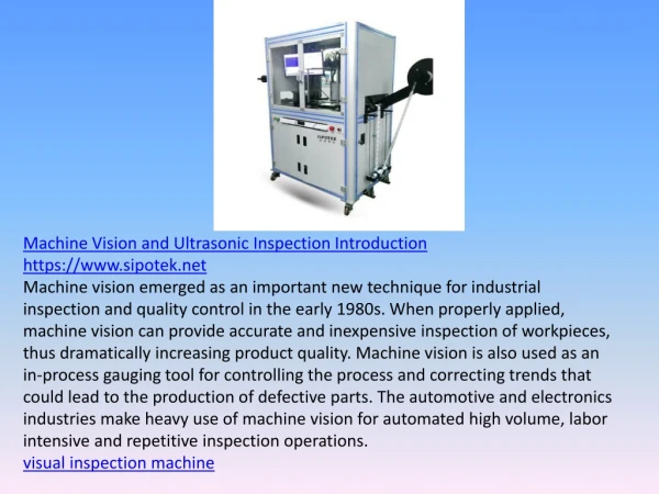
A machine vision system often includes the following elements: • Image Acquisition (generally from a camera placed above the production line), • Image Pre-Processing (e.g. increasing the contrast, motion de-blur, etc), • Feature Extraction (e.g. measuring a distance, checking a screw is in place etc), • Decisions (i.e. is the part OK to a tolerance, is a label in the correct position), and, • Control (e.g. give the result to a Programmable Logic Controller (PLC) or robot controller).
Image Acquisition • Transforms the visual image of a physical objects into a set of digitized data • Illumination • Image formation (including focusing) • Image detection or sensing • Formatting camera output signal
Image Formation and Detection Image is formed by: • Illumination flux from object • Optics (lens) • Photosensitive detectors (photodiodes on solid state cameras) Vision systems have an optical-electro device that converts electromagnetic radiation from the image of the physical object into an electric signal used by the vision processing unit
Vision – Image Formation • Shape • Lighting • Relative Positions • Sensor sensitivity Same shape – very different images!
Structured Lighting Diffuse Backlighting Directional backlighting Fiber-optic/LED ring lights Lighting
Polarized lighting Oblique lighting Direct front lighting Cross polarization Lighting
Diffuse front lighting Dark field illumination Fibre optic near in-lighting Lighting
Image Formation and Detection Light source
Digitization of Camera Signal • Analog image data (voltage) is sampled and quantized (often to 8 bits greyscale or 24 bits of color)
Software: Processing the Data • The software allows the image to be processed, analyzed, and stored. • Different types of software packages are available, ranging from easy-to-use packages with pre-defined tools, to SDKs (software development kits) that allow programmers to build custom imaging applications. • Matlab™ has an image processing tool box • Image Pre-processing • Feature Extraction
Image Pre-processing • What to do with the image? • May need to preprocess the image in order to analyze it • Remove motion blur (ECE 533/738) • Enhance contrast
I Can See It – Why can’t the Computer? • Minimize possible problems – The human eye and brain are elaborate and versatile systems, capable of identifying objects in a wide variety of conditions. For example, we are able to identify familiar people even when they are wearing different clothes, and recognize familiar landmarks when driving on a foggy day. A PC-based imaging system is not as versatile; it can only perform what it has been programmed to perform. Knowing what the system can and cannot "see" are important points to keep in mind to obtain the results you want, and reduce errors and incorrect measurements. Common variables include: ·Changes in object’s color ·Changes in surrounding lighting ·Changes in camera focus or position ·Improperly mounted camera ·Environmental vibration • A vibration-free environment with all extraneous light removed will eliminate many common problems.
Find the man…. Visual tasks can be made difficult!
Distractors Natural systems take advantage of the fact that visual tasks can be made difficult!
I Can See It – Why can’t the Computer? • Minimize possible problems – • Knowing what the system can and cannot "see" are important points to keep in mind to obtain the results you want, and reduce errors and incorrect measurements. Engineer the environment! Great examples include commercial motion capture systems
Feature Extraction/Analysis • 2D Geometric Analysis: • Must have high contrast to separate (“segment”) part from background • In practice back lighting is often used • The silhouette is used to determine: • part dimensions: Width, height, orientation, etc • Part features (e.g. number of holes) • Relationships between parts
Controlled Environment Easy to “segment” image
Measurements from Images • Must have relationship between the image “pixels” and the world • 2D imaging • the image plane and the “world” plane are in 1-1 correspondence • 3D –harder
Modeling Cameras Basic of pinhole Kinematics of Vision Coordinate transformations Processing Images Some simple features (sections 8.13 - 8.25) 2D problems Modeling Cameras Pinhole model Projective mapping Calibration Procedures Kinematics of Vision Coordinate transformations Motion field equations Processing Images Feature detection (lines, blobs) Visual Servoing (Eye-Hand Coordination) in 3D Goals for ME 439 and ME 739