An Introduction to Grinding Machine Control Systems
220 likes | 386 Vues
An Introduction to Grinding Machine Control Systems. John Moruzzi AMTReL. Director of Studies: Dr Michael Morgan. Personal Introduction . John Moruzzi BSc Electrical Engineering & Electronics University of Leeds MSC Computational & Statistical Modelling University of Liverpool

An Introduction to Grinding Machine Control Systems
E N D
Presentation Transcript
An Introduction to Grinding Machine Control Systems John Moruzzi AMTReL Director of Studies: Dr Michael Morgan An Introduction to Grinding Machine Control Systems
Personal Introduction John Moruzzi BSc Electrical Engineering & Electronics University of Leeds MSC Computational & Statistical Modelling University of Liverpool Known AMTReL since early 90’s Software engineering Aerospace / Avionics Manufacturing / Machine Tools OMR / OCR Applications Electrical installation Commercial / Industrial Technical sales / support Grinding machine process control (Balance Systems) An Introduction to Grinding Machine Control Systems
AMTReLJones & Shipman 1300X • Universal grinding machine • External and Internal wheelheads • SAMM control (Servo Assisted Manual Machine) • Prototype machine based on Format 15 model • Built circa 1994, modified 2001 • Closed control system – Industrial PC / MS-DOS Used for previous AMTReL projects/PhD’s Adaptive control (Y Chen) Open CNC Interface (C Statham) High speed Internal grinding Industry co-operations (Timken, Lucas, …) Fluid delivery methods, nozzle design AE monitoring Dressing tool control (fluid coupling) An Introduction to Grinding Machine Control Systems
Objectives Machine Re-commission hardware Move axes Replace workhead drive Modifications to wiring Disable hardware limitations Remove original control panel Implement simplified control panel Interface external devices Control system Initial “desktop” PC control : ISA bus motion control card ISA bus Digital I/O card Standard mouse / keyboard / monitor Initial software Windows 2000 (XP), Visual Basic Programming familiarity Axis configuration Axis movements Simple grinding cycles Simple cycle programming Simple IO features An Introduction to Grinding Machine Control Systems
Machine Tool Axes Cylindrical (Universal) grinding machine Z axis - horizontal (table) positioning of workpiece for grinding X axis - radial (wheelfeed / infeed) application of wheel for grinding C axis - workpiece rotation (workhead) fixed between headstock and tailstock Surface grinding machine X axis - horizontal (table) oscillation of workpiece for grinding Y axis - vertical (“downfeed”) application of wheel for grinding Z axis - workpiece incremental translation (saddle) clamped to table An Introduction to Grinding Machine Control Systems
Axis positioning and control Position measurement Encoder linear scale or rotary 2 quadraturepulsetrains Marker / Zero pulse distance moved and direction Configuration Scaling (pulses / rev, pulses / mm) Thread pitch Limits Axis overtravel switches / signals (+ve, –ve) Axis movement Motion control hardware Position target, move speed Position feedback (speed) Speed reference signal Servo drive Speed reference input (DC +/- 10V) Motor power output (DC / AC) Scaling, Trim, Offsets Servo motor Resolver feedback (speed) Ballscrew An Introduction to Grinding Machine Control Systems
Wheelspeed and Workspeed Wheelspeed Rotational speed (RPM) Surface speed (m/sec) Fixed on simple machines , can be changed with gearing / pulleys Variable on more sophisticated machines, can be adjusted for “constant speed” machining Workspeed Rotational speed (RPM) Surface speed (m/sec) Variable on most grinding machines Controlled by operator / program Open-loop motor drive control N.B. Relationship between wheel speed and workpiece speed crucial to the grinding process An Introduction to Grinding Machine Control Systems
Common grinding cycles Dressing Single point “diamond” dressing: Wheel rotating (surface speed vc ) Wheel traverses past diamond tip (crossfeed velocity vf) Wheel infeeds an increment (infeed amount ad) Repeat until wheel surface fully dressed Plunge grindingWorkpiece / table positioned relative to wheel Wheel and workpiece rotating (vc and vw) Wheel infeed at Rapid speed to start position (dia) Wheel infeed at Coarse feed to Fine Feed start position (dia) Wheel infeed at Fine feed to Final Size position (dia) Sparkout or Dwell with no infeed Traverse grindingWorkpiece / table set to oscillate across wheel to wheel Wheel and workpiece rotating (vc and vw) Wheel infeed by Rapid increments to start position (dia) Wheel infeed by Coarse increments to Fine Feed start position (dia) Wheel infeed at Fine feed to Final Size position (dia) Sparkout passes of wheel with no infeed An Introduction to Grinding Machine Control Systems
Cycle programming - 1 CNC part-programming Sequence of instruction lines or “blocks” M-codes functional commands G-codes movement commands Canned cycles complex operations (machine specific) M-codes M02 End of Program M03 Spindle on (CW rotation) M05 Spindle Stop M07 Coolant on (flood) M09 Coolant off G-codes G00 Rapid positioning G01 Linear interpolation G28 Return to home position Canned cycles (J & S Series 10) G86 Traverse Grinding G88 Plunge Grinding G88 X25.4 Z50.000 D0.50A0.010 B0.02 C0.0005 P25.5 J25.410 S10 Q0 An Introduction to Grinding Machine Control Systems
Cycle programming - 2 Guided / Teaching process Manually move to position, save values Enter / adjust values (keypad, buttons) Plunge cycle Go to Z start pos: <Enter> Go to X size pos: <Enter> Go to X start pos: <Enter> Go to X finefeed pos: <Enter> Program X coarse feedrate <Enter> Program X fine feedrate <Enter> Program Sparkout time <Enter> Traverse cycle Go to Z right pos: <Enter> Go to Z left pos: <Enter> Go to X size pos: <Enter> Go to X start pos: <Enter> Go to X finefeed pos: <Enter> Program X coarse increment <Enter> Program X fine increment <Enter> Program sparkout passes <Enter> Set Z traverse speed An Introduction to Grinding Machine Control Systems
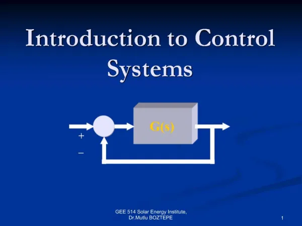
Architecture of a CNC system Main Control ExecutorScheduling, program execution, monitoring IO routines HMI, programming, Digital, Bus Safety Machine logic Cycle management Sequencing, monitoring Motion ControlAxis movements, motors Process optimisation In-process Gauging Diameter, Shoulder Touch Detection AE, Power Wheel balancing Auto / Manual Probing Adaptive / Intelligent Control Adaptive strategy Parameter modification Selection strategy Rule / Case based Process models & rules Kinematic, Compliance Database Learning strategy, data An Introduction to Grinding Machine Control Systems
Jones & Shipman Ultramat Left-Hand operator panel Manual/ Automatic mode Operation selection – Dress / Plunge / Traverse Program upload / download Linked cycle select Z axis DRO, MPG and scale setting Feedrate Override switch Key enable Cycle interrupt / repeat Traverse hold / dwell Z axis reverse / jog E-stop button Control On button An Introduction to Grinding Machine Control Systems
Jones & Shipman Ultramat Right-hand control panel • X axis DRO, MPG and scale setting • Wheelguard raise, Workhead airlift & unclamp • Gauge apply, Dresser raise • Coolant On/Off, Wheel On/Off, Workhead On/Off • Cycle Start/Stop • “Easy” Touch screen • Program / cycle selection • Data entry • Numeric keypad • Navigation • Operator information • Machine setup An Introduction to Grinding Machine Control Systems
Machine control comparison J&S 1300X – CT, bespoke 2 x Axis drives 1 x workhead drive IO interfacing with terminal blocks 3-phase / 1 phase transformers J&S Ultramat– Fanuc Processor module Axis / workhead drives IO interfacing modules Ethernet / RS232 / USB An Introduction to Grinding Machine Control Systems
Current control hardware – 1300X 4 x Axis encoder inputs X axis, Z axis position X axis, Z axis MPG commands 3 (4) Axis speed control outputs X axis, Z axis speed Workhead (C axis) speed 48 Opto-isolated digital IO 18 inputs (24) 8 outputs (24) RS-232 interface panel display data (out) panel control commands (in) Industrial PC case Motion control card Digital IO card CPU card Power supply An Introduction to Grinding Machine Control Systems
Servo Motion control Servo Drive Motion control Kv : Derivative Gain Speeddem = (Posmodel –Posactual) x Kv Speeddem Posactual Posdemand Veldemand Velactual Encoder Servo Motor Transmission An Introduction to Grinding Machine Control Systems
Deva 004 : X, Z axis setup Z axis PITCH = -10.0000 MAXVOLT = 3000 (2150) COUNT = 10000.0000 MAXSPEED = 60 MAXACCEL = 60 GAIN KV = 15 SPEED = 25 X axis PITCH = -5.0000 MAXVOLT = -3000 (-3850) COUNT = 10000.0000 MAXSPEED = 60 GEARING = 1:1.29 MAXACCEL = 60 GAIN KV = 45 SPEED = 50 An Introduction to Grinding Machine Control Systems
Initial software An Introduction to Grinding Machine Control Systems
Process / Cycle parameters Plunge PlungeCoarseInfeed As Double PlungeFineInfeed As Double PlungeFineDia As Double PlungeStartDia As Double PlungeSizeDia As Double PlungeDwell As Double Axis X0DatumPosition As Double XHomePosition As Double XZeroPosition As Double XAbsolute As Double Z0DatumPosition As Double ZRevDatumPosition As Double ZHomePosition As Double ZAbsolute As Double Motion dblXMovespeed As Double dblXRapid As Double dblXCoarseFeedAs Double dblXFineFeed As Double dblXInfeed As Double dblXInfeedRate As Double intXDwell as Integer dblXStartPosition As Double dblXFinePosition As Double dblXSizePosition As Double dblZReversePositionL As Double dblZReversePositionR As Double dblZStartPosition As Double intFROSetting As Integer blnFeedHold As Boolean Traverse XCoarseInc As Double XFineInc As Double TraverseZFeed As Double TraverseStartDia As Double TraverseFineDia As Double TraverseSizeDia As Double Z0Dwell As Double ZRevDwell As Double TraversePasses An Introduction to Grinding Machine Control Systems
New Components • Workhead servo drive • Industrial PC • Motion control card • Touchscreen monitor • Console switches / lamps • Cabling / connectors An Introduction to Grinding Machine Control Systems
Progress So far..... Reactivation of machine tool Minor electrical modifications Development software with “old” hardware Familiarity with motion control package Implementation of simple cycles Axis configuration and movement Specification and ordering of equipment Initial interface design Next steps.... Commissioning of workhead drive Axis movement via MPGs: Incremental Rapid Digital IO Equipment control Axis limits etc. PCI motion card Cabling Control panel Initial demonstration software An Introduction to Grinding Machine Control Systems
And finally... Thank you..... An Introduction to Grinding Machine Control Systems