Ideal Grounding Scheme for 50Ω Microstrip and Twisted Pair Signal Transmission
This document discusses the impedance configurations for a 50Ω microstrip and a 50Ω twisted pair cable spanning lengths between 5.1 to 6.1 meters. It highlights the existing grounding scheme where both cable ends are grounded, which can introduce noise and voltage interference to the signal threshold at the comparator input. The preferred approach is suggested to involve breaking this ground connection at the Field Effect Transistor (FEE) boards to mitigate external voltage/noise influence, enhancing signal integrity during transmission.

Ideal Grounding Scheme for 50Ω Microstrip and Twisted Pair Signal Transmission
E N D
Presentation Transcript
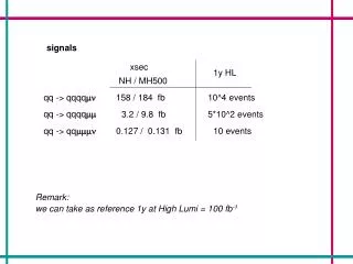
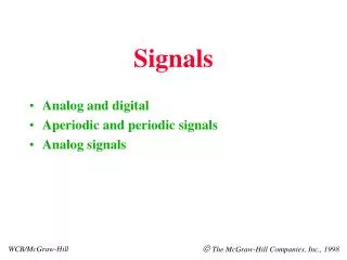
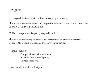
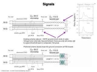
Signals Z0= 50 Ω microstrip Z0= 113 Ω twisted pair 50 Ω Length 5.1 – 6.1 m 50 Ω Existing scheme (above) – NOTE ground at both ends of cable. Voltage/noise externally imposed between these grounds will simply add to signal+threshold input to comparator. Not great. Preferred scheme would break this ground connection at FEE boards: Z0= 50 Ω microstrip Z0= 113 Ω twisted pair 50 Ω Length 5.1 – 6.1 m 50 Ω