Download
1 / 59
740 likes | 1.26k Vues
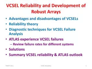
VCSEL Reliability and Development of Robust Arrays. Advantages and disadvantages of VCSELs Reliability theory Diagnostic techniques for VCSEL Failure Analysis ATLAS experience VCSEL failures Review failure rates for different systems Solutions Summary VCSEL reliability & ATLAS outlook.

E N D
VCSEL Reliability and Development of Robust Arrays • Advantages and disadvantages of VCSELs • Reliability theory • Diagnostic techniques for VCSEL Failure Analysis • ATLAS experience VCSEL failures • Review failure rates for different systems • Solutions • Summary VCSEL reliability & ATLAS outlook VCSEL Reliability
Advantages of VCSELs • Low thresholds low power consumption • Circular beam easier to couple to fibres • ~ 10,000 VCSELs on wafer. Test at wafer level only package good devices saves costs (compared to edge emitters) Oxide implant provides current confinement & waveguide lower threshold current VCSEL Reliability
Problems with VCSELs • Difficult to make reliable semiconductor lasers because minority carrier concentrations and recombination rates 100s times higher than in Si ICs • Minority carriers cause defects to grow and kill laser need to start with nearly perfect device • Resources available to companies making lasers (~10M$) << silicon ICs (~10B$) • GaAs used for 850 nm VCSELs, allows Dark Line Defects to grow (unlike InGaAsP in EEL) • Difficult but not impossible to make reliable VCSELs • Many trade-offs for speed/reliability e.g. oxide aperture, drive current … VCSEL Reliability
Reliability Theory • Distinguish different failure times • Infant mortalities • Maverick failures • End of life (wear out) failures • Need diagnostic tools to identify causes failures Failures 1 3 2 Time VCSEL Reliability
Physics of Failure Modes • GaAs lasers sensitive to growth of Dark Line Defects • Defects act as centres for non-radiative transfers • DLDs can come from substrate defects or damage: • Electro Static Discharge/Electrical over Stress • Mechanical, eg wafer handling, dicing or wire bonding • DLDs • grow rapidly in active region from carrier recombination at trap sites • away from active region grow slowly by spontaneous emission e h pairs DLDs grow towards the active area • Slow growth of damage can be undetected, followed by rapid death VCSEL Reliability
Wearout Failures • No change in active regions for devices that have degraded in long term aging tests • Current shunting hypothesis: • Dopants are passivated by complexes with H • Pushes current away from centre of device increases laser threshold and lowers efficiency • Not directly proven VCSEL Reliability
Some Diagnostic Techniques(see backup for more) • Electroluminescence (EL) • Image emitting area when laser operated below threshold • Sensitive to Dark Line Defects • Can improve resolution with filters • Select l=50 nm below emission wavelength reduces number of “bounces” photons make in cavity • More information in shape of line scans • Examples from ATLAS VCSEL failures next slide VCSEL Reliability
Electroluminescence for Failed VCSEL (ATLAS LArOtx) Overlay: Optical and Emission Low Level Emission Image Possible scratch on surface Speckled emission pattern Analysis by Sandia VCSEL Reliability
IV Curves Truelight VCSEL array 1 dead channel • Forward IV • One dead channel clearly shifted IV • General feature for any dead VCSEL • Reverse IV • Reverse leakage below breakdown >> after low level ESD • More sensitive to low level (300V) ESD V I (mA) VCSEL Reliability
Electron Beam Induced Current (EBIC) • Add sensitive amplifier to Scanning Electron Microscope and measure current as e beam is scanned • e beam generates e h pairs measure current • Damaged areas (eg DLDs) have carrier recombination at defects trap e and holes reduce current • SEM Voltage determines depth of primary beam • More information from scans with forward and reverse bias • Depletion region extends into n and p regions • Not normally used for VCSELs because scatter from contact metal degrades resolution but … VCSEL Reliability
EBIC comparison working & Failed channels TL VCSEL array Dead Working • All taken with same SEM settings: 10KV spot 5 (roughly same mag 4700X and 5000x) • Original Image LUTs stretched to accentuate EBIC changes across VCSELs • Only Ch 10 shows distinct EBIC minima (dark spots) within the emission region • Ch 06 & 08 show some inhomogeneity but no distinct minima • Small dark speckles are surface topography Analysis by EAG VCSEL Reliability
Transmission Electron Microscopy (TEM) • Plan view TEM can image full area of active region over narrow range in depth • X-section TEM • Can see defects in different layers • Requires sample preparation: FIB to produce ~ 1um thick sample requires localisation of defects with other techniques eg EBIC or EL (or luck) • ATLAS examples in next slides VCSEL Reliability
STEM Unused ChannelTL VCSEL array after FIB cut Top DBR oxide MQW (active region) Bottom DBR Analysis by EAG VCSEL Reliability
STEM Failed ChannelTL VCSEL array after FIB cut DBR Defects at edge of Oxide DBR active MQW region Oxide MQW VCSEL Reliability Analysis by EAG
Used Working Channel Plan View SEM Dislocations starting to form on edge of aperture Analysis by EAG VCSEL Reliability
Optical Spectrum Analysis (OSA) • Powerful diagnostic technique used extensively by ATLAS • In-situ, non-destructive • Can detect very early signs of damage • VCSEL spectra show multiple transverse modes (single longitudinal mode) • Loss of higher order modes gives early indication of damage long before power decreases VCSEL Reliability
VCSEL Spectrum • VCSELs single longitudinal mode but multiple transverse modes • Many weak higher order modes visible • Loss of higher order modes is early warning • Need to define width: use width @ peak -30dBm VCSEL Reliability
Warning • Sometimes possible to uniquely diagnose cause of failure, e.g. ESD or mechanical damage • But despite having array of beautiful diagnostic techniques available it is often not possible to uniquely determine causes of failures Fused quantum wells 500V HBM ESD event VCSEL Reliability
Accelerated Aging Tests (1) • Require lifetimes ~ 10 years need accelerated aging tests to validate designs • Measure Mean Time To Failure at several elevated temperature/current and use Arrehnius equation for Acceleration Factor from (I2,T2) to (I1,T1) Activation energy: EA VCSEL Reliability
Accelerated Aging Tests (2) Failures versus time Acceleration Model Fit MTTF vs T: extrapolation from elevated I & T to operating conditions Assumes one dominant failure mechanism • Log-normal fits to data at fixed I and T MTTF • T= 150,130,110 & 90C ULM VCSELs 50 Failure (%) Emcore VCSELs Time (h) VCSEL Reliability
VCSEL Reliability in ATLAS VCSEL Reliability
ATLAS LAr • OSA revealed two populations Failed devices nearly all show narrow spectral widths Width (nm) Remaining devices with narrow widths removed during 2011 shutdown No failures seen since Serial number VCSEL Reliability
Possible Causes (1) • ESD • VCSELs known to have very low ESD thresholds • ESD most common cause of field failures for VCSELs • Controlled low level ESD pulses can cause a decrease in spectral widths VCSEL Reliability
Possible Causes (2) • Humidity (TO can should be hermetic but suspect some damage during assembly) • Deliberately opened TO can • Operation of VCSEL in lab environment with RH ~ 55% shows decrease in spectral width VCSEL Reliability
Pixel & SCT TXs • End of life failures experienced after ~ 6 months • ESD suspected during assembly all devices replaced with greatly improved ESD precautions • Lifetimes improved but still << 10 years required for ATLAS operation Original production Improved ESD Precuations VCSEL Reliability
Humidity Hypothesis • Single channel VCSELs usually packaged in hermetic TO cans • Very difficult to package arrays in hermetic packages • Reliability of first arrays in damp environments was poor (lifetimes ~ 100 hours at 85C/85% RH) • Electrolytic corrosion hypothesis: • Moisture depletes As in oxide layer excess Ga point defects which grow toward active area VCSEL Reliability
RH and Lifetime Correlation • Use (accidental) fact that RH was different for some SCT crates • Weibull fits to failures Mean Time To Failure • Correlation with RH similar to that reported in literature VCSEL Reliability
Accelerated Aging Tests Very short MTTF Epoxy only delays humidity entering VCSEL VCSEL Reliability
Humidity Tests • 85/85 test is extreme, so how do we know that humidity is the main cause of death? • Use OSA to look at spectral narrowing for • TX VCSELs in dry N2 • TX VCSELs in lab RH air VCSEL Reliability
Widths clearly decreasing VCSEL Reliability
Widths ~ constant VCSEL Reliability
Example Spectra • Air ~ 50% RH • Loss of higher order modes visible • Dry N2 • Higher order modes very similar VCSEL Reliability
Pixel On-detector VCSEL • Same Truelight VCSEL array/MT package as for the SCT/Pixel off-detector arrays which are failing • But inside detector very low RH • Accelerated aging tests for Truelight arrays at low RH: no deaths for 24 channels, T=85C, I=10 mA , 2100 hours lower limit on lifetime = 49 years Optical Power (mW) Electrical disconnects Time (h) VCSEL Reliability
Solutions for Humidity Problems • Some manufacturers claim to make VCSELs that are reliable in high RH • Details commercially sensitive but principle measure is blocking holes used for steam to grow oxide layer with a dielectric layer • AOC and ULM have made VCSELs that pass 1000 hours of 85C/85% RH should be ok for 10 years operation in normal lab environment VCSEL Reliability
Reliability Tests • Bare AOC arrays • I=8 mA DC, 85C/85% RH • No deaths for 31 channels after 3200 hours • AOC arrays packaged by CSIST • I=10mA DC, 70C/85% RH, 60 channels used • No significant change in spectral widths for 2000 hours Initial increase when T increased from 20C to 70C VCSEL Reliability
iFlame • Semi-hermetic package • Small form-factor compatible with ATLAS SCT/Pixel TX PCBs • Uses ULM (ViS) VCSEL which also passes 1000 hours of 85C/85% RH • We will repeat lifetime tests with OSA 4 channel TRx ATLAS 12x in production VCSEL Reliability
VCSEL Reliability Summary • Manufacturers have succeeded in making reliable VCSELs but beware of sensitivity to environmental factors • Mechanical • Thermal • ESD/EoS • Humidity • OSA powerful diagnostic technique • Some manufacturers have improved moisture protection can use these VCSEL arrays in non-hermetic packages VCSEL Reliability
ATLAS Outlook • LAr Calorimeter: • replaced suspect channels in last winter shutdown • No VCSEL deaths in 2011 • Backup schemes available if required (uses redundancy) • SCT/Pixel off-detector TXs • All devices being replaced with two solutions: • AOC packaged by CSIST • ULM(ViS) VCSELs packaged in iFlame VCSEL Reliability
Institutes Involved • Academia Sinica • Bergische Universität Wuppertal • Columbia University, Nevis Laboratories • Laboratoire de l'Accelérateur Linéaire d'Orsay (IN2P3-LAL) • Lawrence Berkeley National Laboratory • Ohio State University • Organisation Européenne pour la Recherche Nucléaire (CERN) • Oxford University • Science and Technology Facilities Council, Rutherford Appleton Laboratory • Southern Methodist University • University of California, Santa Cruz • Università degli Studi di Genova • Universität Siegen VCSEL Reliability
Backup Slides VCSEL Reliability
Other Diagnostic Techniques • TIVA • CL VCSEL Reliability
Cathode Luminescence • Light generated in SEM (cf EBIC) • Light emerges from all layers that have a direct bandgap • Defects create non-radiative traps images dark in these regions • Bandpass filter can resolve one feature Arrows indicate dark line defects VCSEL Reliability
Thermally Induced Voltage Analysis • Laser Scanning Microscopy • If photon energy > bandgap e/h pairs cf EBIC • If photon energy< bandgap local change in T creates local changes in resistance • Constant current source supplies bias that results in voltage variation with resistance changes • Scan surface and measure R (use constant current source) VCSEL Reliability
TIVA Example (Agilent) VCSEL Reliability
TIVA LAr OTx Optical image TIVA @ 10 nA Dark lines and spots believed to be defects in MQW VCSEL Reliability
U-L-M VCSEL VCSEL Reliability
iFlame VCSEL Reliability
iFlame VCSEL Reliability
IV Analysis • Forward IV curve changes with VCSEL death because device dominated by non-radiative rather than radiative recombination • Simple indicator of VCSEL death but doesn’t tell you anything about the cause • Reverse IV curve • Dead devices can show large increases in reverse current below breakdown voltage • Very sensitive to low level ESD but can’t prove ESD VCSEL Reliability
LAr OTx: exposed to RH • LI curves develop kinks: indication of damage VCSEL Reliability