VCSEL Reliability & Understanding Failure Mechanisms under Humidity
1.12k likes | 2.12k Vues
VCSEL Reliability & Understanding Failure Mechanisms under Humidity. European VCSEL Day 2013 Tony Weidberg (Oxford) on behalf of the ATLAS collaboration. VCSELs @ LHC. VCSELs used for readout of all detector systems in the ATLAS experiment @ CERN LHC.

VCSEL Reliability & Understanding Failure Mechanisms under Humidity
E N D
Presentation Transcript
VCSEL Reliability & Understanding Failure Mechanisms under Humidity European VCSEL Day 2013 Tony Weidberg (Oxford) on behalf of the ATLAS collaboration European VCSEL Day 2013
VCSELs @ LHC • VCSELs used for readout of all detector systems in the ATLAS experiment @ CERN LHC. • This talk will focus on the systems which showed the highest failure rates and out attempts to understand the cause(s). • VCSELs used for data transmission from silicon detectors counting room electronics. • Large system based on ~ 600 * 12 way VCSEL arrays. European VCSEL Day 2013
ATLAS Silicon Strip Detector • 4088 silicon strip modules. • Assembled onto layers of carbon fibre support structures. • Inserted in ATLAS. European VCSEL Day 2013
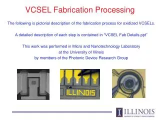
OSA produced by Academia Sinica/CSIST Epoxy Epo-Tek 353ND over active surface of VCSEL Truelight array TSA-8B12-00 Jig used for precision placement of array wrt guide pins MT-connector inside Infineon housing with spring ATLAS VCSEL Meeting 19/8/10
Off-Detector Optoelectronics • VCSEL array on and driver chip on PCB • Mounted in 9U VME crate. • 48 TX and 96 RX channels small form factor vital. European VCSEL Day 2013
Failure Rates in ATLAS Operation European VCSEL Day 2013
Accelerated Aging Tests • Measure Mean Time To Failure at several elevated temperature/current and RH use Arrehnius equation for Acceleration Factor from (I2,T2) to (I1,T1) Activation energy: EA and exponential for relative humidity (RH). European VCSEL Day 2013
Fit Results EA=0.72 eV a = 0.059 (/%) European VCSEL Day 2013
Physics of Failure Modes • GaAs lasers sensitive to growth of Dark Line Defects • Defects act as centres for non-radiativetransfers. • DLDs can come from substrate defects or damage. • Electro Static Discharge/Electrical over Stress. • Mechanical, eg wafer handling, dicing or wire bonding. • DLDs • grow rapidly in active region from carrier recombination at trap sites. • away from active region grow slowly by spontaneous emission e h pairs DLDs grow towards the active area. • Slow growth of damage can be undetected, followed by rapid death. European VCSEL Day 2013
Failure Analysis • ALT results suggest damage caused by humidity. • TL VCSEL designed for use in hermetic TO can and is not humidity resistant. • Controlled tests with OSA to measure spectral widths. • Detailed post-mortem analysis to determine cause(s) of failures. European VCSEL Day 2013
VCSELs in air show decrease in width with time and then plateau VCSELs in dry N2 show no decrease in width with time European VCSEL Day 2013
EBIC comparison working & Failed channels TL VCSEL array Dead Working • All taken with same SEM settings: 10KV spot 5 (roughly same mag 4700X and 5000x) • Original Image LUTs stretched to accentuate EBIC changes across VCSELs • Only Ch 10 shows distinct EBIC minima (dark spots) within the emission region • Ch 06 & 08 show some inhomogeneity but no distinct minima • Small dark speckles are surface topography Analysis by EAG European VCSEL Day 2013
STEM Unused ChannelTL VCSEL array after FIB cut Top DBR oxide MQW (active region) Bottom DBR Analysis by EAG European VCSEL Day 2013
STEM Failed ChannelTL VCSEL array after FIB cut DBR Defects at edge of Oxide DBR active MQW region Oxide MQW European VCSEL Day 2013 Analysis by EAG
Used Working Channel Plan View SEM Dislocations starting to form on edge of aperture Analysis by EAG European VCSEL Day 2013
Humidity Damage Hypothesis • Cracking at oxide aperture tip causes defects that propagate down into the active region • when they cross the active region, they nucleate the dark-line defect network rapid catastrophic failure. • Evidence for a galvanic process: • VCSELs aged in 85C/85% RH and then operated under 85C/0% RH showed no failures. • Damage too extensive to localise origin. European VCSEL Day 2013
More Controlled Tests • Aged VCSEL array in 70C/85% RH with regular power measurements and EL imaging. • Stopped as soon as significant decrease in power detected. • EL image shows 4% of area is dark. • Subsequent TEM analysis (next slides). European VCSEL Day 2013
Plan View TEM • Dislocations in dark region from EL • Two dislocations emanating from tip of Oxide. Zoom European VCSEL Day 2013
X-Section TEM • X-section views • after thinning to ~ 1.8 um (“thick”). • after further thinning to ~ 0.8 um. This allows tracing of defects. European VCSEL Day 2013
Tracing Defects • line dislocations starting from oxide tip (crack?). • traveled down from oxide aperture active region below, and started the DLD network. • Note lines travel up before looping down (follow current wind). European VCSEL Day 2013
Summary • VCSEL damage under humidity studied by: • ALT statistical analysis acceleration model; • OSA; • TEM analysis failed samples; • Mildly degraded sample. • Damage is galvanic process. • Confirmed hypothesis that damage starts at tip of oxide aperture and DLD grow towards active MQW region and kills device. European VCSEL Day 2013
Backup Slides European VCSEL Day 2013
Electron Beam Induced Current (EBIC) • Add sensitive amplifier to Scanning Electron Microscope and measure current as e beam is scanned • e beam generates e h pairs measure current • Damaged areas (eg DLDs) have carrier recombination at defects trap e and holes reduce current • SEM Voltage determines depth of primary beam • More information from scans with forward and reverse bias • Depletion region extends into n and p regions • Not normally used for VCSELs because scatter from contact metal degrades resolution but … European VCSEL Day 2013
Transmission Electron Microscopy (TEM) • Plan view TEM can image full area of active region over narrow range in depth • X-section TEM • Can see defects in different layers • Requires sample preparation: FIB to produce ~ 1um thick sample requires localisation of defects with other techniques eg EBIC or EL (or luck) • ATLAS examples in next slides European VCSEL Day 2013
Example Spectra • Air ~ 50% RH • Loss of higher order modes visible • Dry N2 • Higher order modes very similar European VCSEL Day 2013
Solutions for Humidity Problems • Some manufacturers claim to make VCSELs that are reliable in high RH • Details commercially sensitive but principle measure is blocking holes used for steam to grow oxide layer with a dielectric layer • AOC and ULM have made VCSELs that pass 1000 hours of 85C/85% RH should be ok for 10 years operation in normal lab environment European VCSEL Day 2013
Reliability Tests • Bare AOC arrays • I=8 mA DC, 85C/85% RH • No deaths for 31 channels after 3200 hours • AOC arrays packaged by CSIST • I=10mA DC, 70C/85% RH, 60 channels used • No significant change in spectral widths for 2000 hours Initial increase when T increased from 20C to 70C European VCSEL Day 2013
VCSEL Reliability Summary • Manufacturers have succeeded in making reliable VCSELs but beware of sensitivity to environmental factors • Mechanical • Thermal • ESD/EoS • Humidity • OSA powerful diagnostic technique • Some manufacturers have improved moisture protection can use these VCSEL arrays in non-hermetic packages European VCSEL Day 2013
ATLAS Outlook • LAr Calorimeter: • replaced suspect channels in last winter shutdown • No VCSEL deaths in 2011 • Backup schemes available if required (uses redundancy) • SCT/Pixel off-detector TXs • All devices being replaced with two solutions: • AOC packaged by CSIST • ULM(ViS) VCSELs packaged in iFlame European VCSEL Day 2013
Institutes Involved • Academia Sinica • BergischeUniversität Wuppertal • Columbia University, Nevis Laboratories • Laboratoire de l'AccelérateurLinéaire d'Orsay (IN2P3-LAL) • Lawrence Berkeley National Laboratory • Ohio State University • OrganisationEuropéenne pour la RechercheNucléaire (CERN) • Oxford University • Science and Technology Facilities Council, Rutherford Appleton Laboratory • Southern Methodist University • University of California, Santa Cruz • UniversitàdegliStudi di Genova • Universität Siegen European VCSEL Day 2013
Some Diagnostic Techniques • Electroluminescence (EL) • Image emitting area when laser operated below threshold • Sensitive to Dark Line Defects • Can improve resolution with filters • Select l=50 nm below emission wavelength reduces number of “bounces” photons make in cavity • More information in shape of line scans • Examples from ATLAS VCSEL failures next slide European VCSEL Day 2013
Electroluminescence for Failed VCSEL (ATLAS LArOtx) Overlay: Optical and Emission Low Level Emission Image Possible scratch on surface Speckled emission pattern Analysis by Sandia European VCSEL Day 2013
Cathode Luminescence • Light generated in SEM (cf EBIC) • Light emerges from all layers that have a direct bandgap • Defects create non-radiative traps images dark in these regions • Bandpass filter can resolve one feature Arrows indicate dark line defects European VCSEL Day 2013
Thermally Induced Voltage Analysis • Laser Scanning Microscopy • If photon energy > bandgap e/h pairs cf EBIC • If photon energy< bandgap local change in T creates local changes in resistance • Constant current source supplies bias that results in voltage variation with resistance changes • Scan surface and measure R (use constant current source) European VCSEL Day 2013
TIVA Example (Agilent) European VCSEL Day 2013
TIVA LAr OTx Optical image TIVA @ 10 nA Dark lines and spots believed to be defects in MQW European VCSEL Day 2013
IV Curves Truelight VCSEL array 1 dead channel • Forward IV • One dead channel clearly shifted IV • General feature for any dead VCSEL • Reverse IV • Reverse leakage below breakdown >> after low level ESD • More sensitive to low level (300V) ESD V I (mA) European VCSEL Day 2013
IV Analysis • Forward IV curve changes with VCSEL death because device dominated by non-radiative rather than radiative recombination • Simple indicator of VCSEL death but doesn’t tell you anything about the cause • Reverse IV curve • Dead devices can show large increases in reverse current below breakdown voltage • Very sensitive to low level ESD but can’t prove ESD European VCSEL Day 2013
LAr OTx: exposed to RH • LI curves develop kinks: indication of damage European VCSEL Day 2013
LAr OTx European VCSEL Day 2013
Dark Line Defects For high radiance devices operated at high current densities, the dominant degradation process is the inhomogeneous development of crystal defects acting as centers for non-radiativerecombinations These defects, which occur also in semiconductor lasers, can be seen under high magnification as dark lines and are therefore often called Dark Line Defects (DLD). The development of DLDs is due to the growth of dislocation networks by a climb mechanism under absorption or emission of point defects, apparently using the energy released under forward bias by non-radiativerecombinationsThe growth and propagation of DLDs starts at initially present material impurities or crystal defects and, by increasing the non-radiativecurrent, decreases the light output of the LED or laser at a fixed forward current. The rate of growth increases with current density and temperature, but seems to be also enhanced by mechanical stress, e.g. due to diode assembly or dicing-induced strain European VCSEL Day 2013
Dark Line Defects Field return: suspected ESD Figure 6: EL image of customer return (left) shows a small dark spot to the left, as well as a larger DLD network to the right. A planview TEM image of the small dark spot shows “punched-out” dislocations which are usually signs of ESD breakdown. European VCSEL Day 2013
Advantages of VCSELs • Low thresholds low power consumption • Circular beam easier to couple to fibres • ~ 10,000 VCSELs on wafer. Test at wafer level only package good devices saves costs (compared to edge emitters) Oxide implant provides current confinement & waveguide lower threshold current European VCSEL Day 2013
Reliability Theory • Distinguish different failure times • Infant mortalities • Maverick failures • End of life (wear out) failures • Need diagnostic tools to identify causes failures Failures 1 3 2 Time European VCSEL Day 2013
Wearout Failures • No change in active regions for devices that have degraded in long term aging tests • Current shunting hypothesis: • Dopants are passivated by complexes with H • Pushes current away from centre of device increases laser threshold and lowers efficiency • Not directly proven European VCSEL Day 2013
Optical Spectrum Analysis (OSA) • Powerful diagnostic technique used extensively by ATLAS • In-situ, non-destructive • Can detect very early signs of damage • VCSEL spectra show multiple transverse modes (single longitudinal mode) • Loss of higher order modes gives early indication of damage long before power decreases European VCSEL Day 2013
VCSEL Spectrum • VCSELs single longitudinal mode but multiple transverse modes • Many weak higher order modes visible • Loss of higher order modes is early warning • Need to define width: use width @ peak -30dBm European VCSEL Day 2013
Warning • Sometimes possible to uniquely diagnose cause of failure, e.g. ESD or mechanical damage • But despite having array of beautiful diagnostic techniques available it is often not possible to uniquely determine causes of failures Fused quantum wells 500V HBM ESD event European VCSEL Day 2013