GATE-LEVEL MODELING
GATE-LEVEL MODELING. (Source: a Verilog HDL Primer by J. Bhasker). Different Levels of Abstraction. Architectural / Algorithmic Level Implement a design algorithm in high-level language constructs. Register Transfer Level


GATE-LEVEL MODELING
E N D
Presentation Transcript
GATE-LEVEL MODELING (Source: a Verilog HDL Primer by J. Bhasker)
Different Levels of Abstraction • Architectural / Algorithmic Level • Implement a design algorithm inhigh-level language constructs. • Register Transfer Level • Describes the flow of databetween registers and how a design processthese data.
Different Levels of Abstraction • Gate Level • Describe the logic gates and theinterconnections between them. • Switch (Transistor) Level • Describe the transistors andthe interconnectionsbetween them.
GATE-LEVEL MODELING • The gate-level modeling describes the available built-in primitive gates and how these can be used to describe hardware.
Multiple-input Gates and, nand, or, nor. xor, xnor These logic gates have only one output and one or more inputs.
Input1 Multiple-input gate Input2 Output A Input3 Multiple-input Gates Syntax: multiple_input_gate_type[instance_name] (OutputA,Input1,Input2,….,Input1); Note: A value z at an input is handled like an x and the output can never be a z.
Examples: and A1 (Out1, In1, In2) ; and RBX (Sty, Rib, Bro, Qit, Fix) ; xor (Bar, Bud[0], Bud[1], Bud[2] ) , (Car, Cut[0], Cut[1] ) , (Sar, Sut[2], Sut[1], Sut[0], Sut[3] ) ;
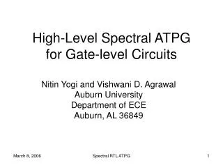
Multiple-output Gates: buf, not These gates have only one input and one or more outputs
Out1 Out2 InputA OutN Out1 Out2 InputA OutN Multiple-output Gates: • Syntax:multiple_output_gate_type[instance_name] (Out1,Out2,…..,OutN, InputA);
Examples:buf B1 ( Fan[0], Fan[1], Fan[2], Fan[3], Clk ) ;not N1 (PhA, PhB, Ready) ;
Tristate Gates: bufif0 , bufif1, notif0, notif1 These gates model three state drivers and have one output, one data input and one control input. Note: • For a bufif0 gate, the output is z if control is 1, else data is transferred to output. • For a bufif1 gate, the output is z if control is 0. • For a notif0 gate, the output is z if control is 1, else output is the invert of the input data value. • For a notif1 gate, the output is z if control is 0.
bufif1 InputA OutputA ControlC bufif0 InputA OutputA ControlC notif1 InputA OutputA ControlC notif0 InputA OutputA ControlC Tristate gates: • Syntax: tristate_gate[instance_name] (OutA, InputB, ControlC); InputAOutputAControlCnotif1
Examples:bufif BF1 ( Dbus, MemData, Strobe ) ;notif0 NT2 (Addr, Abus, Probe) ;
Pull Gates: pullup , pulldown These gates have only one output with no inputs. Note: • A pullup gate places a 1 on its output. • A pulldown gate places a 0 on its output. Syntax: pull_gate_type[instance_name](OutA); Examples: Pullup PUP(Pwr) ;
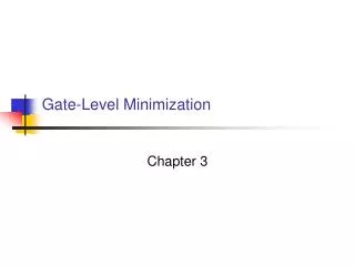
MOS switches: cmos, pmos, nmos, rcmos, rpmos, rnmos These gates model unidirectional switches, that is, data flows from input to output and the data flow can be turned off by appropriately setting the control input(s). Note: • The pmos( p-type MOS transistor), nmos(n-type MOS transistor), rnmos( r stands for resistive) and rpmos switches have one output, one input, and one control input. • If control is 0 for nmos and rnmos switches and 1 for pmos and rpmos switches, the switch is turned off, that is, output has a value z; if control is 1, data at input passes to output.
MOS switches: • Syntax: gate_type[instance_name](OutputA, InputB, ControlC); InputB OutputA InputB Output A ControlC ControlC nmos switch nmos switch
Examples:pmos P1( BigBus, SmallBus, GateControl) ;rnmos RN1(ControlBit,ReadyBit,Hold) ; ( r ) cmos switch Pcontrol InputB OutputA Ncontrol
Bidirectional switches: • tran, rtran, tranif0, rtranif0, tranif1, rtranif1 • These switches are bidirectional, that is, data flows both ways and there is no delay when data propagates through the switches. The last four switches can be turned off by setting a control signal appropriately. The tran and rtran switches cannot be turned off. If control is 1 for tranif0 and rtranif0, and 0 for tranif1 and rtranif1, the bidirectional data flow is disabled. • Syntax : gate_type[instance_name](SignalA, SignalB, SignalC);
Gate Delays • The signal propagation delay from any gate input to the gate output can be specified using a gate delay using the syntax: gate_type[delay] [ instance_name] ( terminal list ); Example: and #3 g (a, b, c);
When no gate delay is specified, the default delay is zero. • A gate delay can be comprised of up to three values: • Rise delay • Fall delay • Turn-off delay
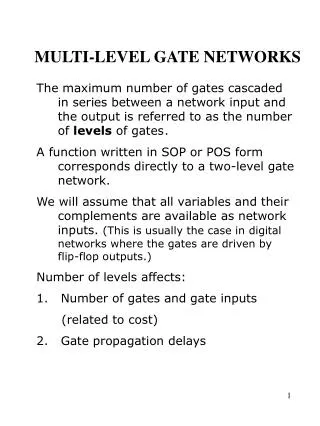
in1 a1 a1_o out iv_sel o1 in2 a2 a2_o n1 sel iv_sel Gate Level Description Gate Level: you see only netlist (gates and wires) in the code.
Gate-Level Modeling • Steps • Develop the Boolean function of output • Draw the circuit with logic gates/primitives • Connect gates/primitives with net (usually wire) • HDL: Hardware Description Language • Figure out architecture first, then write code.
Test Methodology • Systematically verify the functionality of a model. • Procedure of simulation • Detect syntax violations in source code • Simulate behavior • Monitor results
Case Study: Full Adder • Co = AB + BCi + CiA 31
Case Study: Full Adder • sum = a b ci 32
Case Study: Full Adder • Full Adder Connection • Instance ins_cfrom FA_co • Instance ins_sfrom FA_sum 33
Testbench for Full Adder module TestBench; reg a,b,ci; wire sum,cout; initial begin $display(“a b ci sum cout"); a = 1'b0; b = 1'b0;ci = 1'b0; #8 $finish; end always #4 b = ~b; always #2 a = ~a; always #1 ci = ~ci; FA_sum U1(sum,a,b,ci,cout); initial $monitor("%b %b %b %b %b“, a, b, ci, sum, cout); endmodule