Chapter 3 Gate-Level Minimization
Chapter 3 Gate-Level Minimization. 3-1 The Map Method. 3-2 Four-Variable Map. 3-3 Five-Variable Map. 3-4 Product of Sums Simplification. Chapter 3 Gate-Level Minimization. 3-5 Don't-Care Condition. 3-6 NAND and NOR Implementation. 3-7 Other Two-Level Implementation.

Chapter 3 Gate-Level Minimization
E N D
Presentation Transcript
Chapter 3 Gate-Level Minimization 3-1The Map Method 3-2Four-Variable Map 3-3 Five-Variable Map 3-4 Product of Sums Simplification
Chapter 3Gate-Level Minimization 3-5Don't-Care Condition 3-6 NAND and NOR Implementation 3-7 Other Two-Level Implementation 3-8 Exclusive-OR Function 3-9 Hardware Description Language
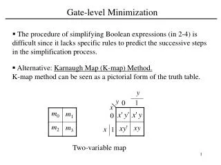
3-1 The Map Method Algebraic Simplification method Map It is awkward because it lacks specific rules to predict each succeeding step in the manipulative process. • Minimum number of terms • fewer possible number of literals in each terms Criteria Simple straightforward
B A A A A B B B 3-1 The Map Method Two-Variable Map mi B A B B 0 1 A m0 0 0 m0 m1 0 m1 0 1 m2 1 0 m2 m3 A AB 1 1 1 m3 Representation of Function in the Map
In a sequence similar to Gray Code 3-1 The Map Method Three-Variable Map BC A 00 01 11 10 0 m0 m1 m3 m2 1 m4 m5 m7 m6 two adjacent squares differ by only one literal, which can be removed when the sum of the two minterms is formed. Example m5 + m7 =xy'z +xyz =xz ( y'+y ) = xz
3-1 The Map Method K map is made of squares. There are 2n squares in the K map for a n-variable function, representing 2n minimum terms respectively; Characteristics Of K map The K-map squares are labeled so that adjacent squares differ only in one variable. adjacent squares: horizontally adjacent squares, vertically adjacent squares, the top-row and bottom-row adjacent squares and the leftmost column and rightmost column adjacent squares.
3-1 The Map Method Example Simplify the Boolean function F(x,y,z) = ( 2, 3, 4, 5) F(x,y,z) = x'y + xy'
3-2 Four-Variable Map Four-Variable Map
Simplifying with K Map: Loop 16 adjacent 1s giving a result of 1 CD AB 00 01 11 10 Loop a quad of adjacent 1s eliminating two variables Loop two adjacent squares eliminating one variable Loop an octet of adjacent 1s eliminating 3 variables 1 00 m0 m1 m3 m2 Four- Variable K Map m4 m5 m7 m6 01 m12 m13 m15 m14 ABD 11 AD m8 m9 m11 m10 10 A 3-2 Four-Variable Map Looping: properly combining any adjacent 2i(i = 1, 2, 3…n)squares in the K map which contain 1s will eliminate i variables.
3-2 Four-Variable Map Prime Implicants A product term obtained by combining the maximum possible number of adjacent squares in the map
Adjacent squares 3-3 Five-Variable Map Map with six or more variables is simplified by computer programs. Five-Variable Map
3-4 Product of Sums Simplification Example: simplify the following in (a) sum of products and (b) product of sums: (a) F=B'D' + B'C' +A'C'D' F'= AB + CD +BD' (b) F =( A'+B') ( C'+D') (B'+D') Applying DeMorgan's theorem
3-4 Product of Sums Simplification Gate implementation
3-5 Don't-Care Conditions Dealing with“Don’t-Care” Conditions Some logic circuits can be designed so that there are certain input conditions which there are no specified output values. In other words, there will be certain combinations of input levels where we “don’t care” whether the output is HIGH or LOW. When simplifying the function, we can choose to include each don't-care minterm either 1's or the 0's, depending on which combination gives the simplest expression.
F = yz + w'z F = yz + w'x' 3-5 Don't-Care Conditions Example : simplify the Boolean function F( w, x, y, z ) =(1,3,7,11,15) which has don't care conditions d(w, x, y, z ) =(0,2,5) Place a "Φ", "d" or "×" in the “don’t care” squares when filling the K map.
3-6 Nand and Nor Implementation NAND Circuits The logic operation of AND,OR and complement can be obtained from NAND gates. Therefore, any digital system can be implemented with NAND gates.
3-6 Nand and Nor Implementation Two equivalent graphic symbols for the NAND gate are shown below, Logically equivalent F= x' +y' + z' =(xyz)' F= (xyz)'
3-6 Nand and Nor Implementation Two-Level Implementation The procedure for implementing a Boolean function with two levels of NAND gates is as follows: • Simplify the function and express it in sum of products. • Draw a NAND gate for each product term of the expression that has at least two literals.
3-6 Nand and Nor Implementation The procedure for implementing a Boolean function with two levels of NAND gates is as follows: • Draw a single gate using the AND-invert or the invert-OR graphic symbol in the second level, with the inputs coming from outputs of first level gates. • A term with a single literal requires an inverter in the first level. It can also be connected directly to an input of the second level NAND gate.
3-6 Nand and Nor Implementation Example: implement the following Boolean function with NAND gates: F(x, y, z) = (1,2,3,4,5,7) F(x, y, z) = xy' + x'y + z
3-6 Nand and Nor Implementation Multilevel NAND Circuits The procedure for converting a multilevel AND-OR diagram into an all-NAND diagram using mixed notation as follows: • Convert all AND gates to NAND gates with AND-inverter graphic symbols. • Convert all OR gates to NAND gates with inverter-OR graphic symbols. • For every bubble that is not compensated by another small circle along the same line, insert an inverter or complement the input literal.
3-6 Nand and Nor Implementation Example:
3-6 Nand and Nor Implementation NOR Implementation The NOR operation is the dual of the NAND operation. Therefore, all procedures and rules for NOR logic are the dual of the corresponding procedures and rules developed for NAND logic.
3-7 Other Two-Level Implementation Wired logic F= (A+B)' +(C+D)' =[ ( A+B) (C+D) ] ' F= (AB)' (CD)'=( AB+CD)'
3-7 Other Two-Level Implementation Nondegenerate Forms 8 nondegenerate form As for four types of gates: AND, OR, NAND and NOR, there are 16 possible combination of two-level forms. Dual AND-OR OR-AND 8 of these combinations are degenerate. NAND-NAND NOR-NOR Dual Dual NOR-OR NAND-AND Dual OR-NAND AND-OR
And-Or-Invert Form NAND-AND Form AND-OR-INVERT Form AND-NOR Form 3-7 Other Two-Level Implementation AND-OR-INVERT Implementation F=(AB+CD+E)'
And-Or-Invert Form F=[ (A+B) (C+D) E]' NOR-OR Form OR-AND-INVERT Form OR-NAND Form 3-7 Other Two-Level Implementation OR-AND-INVERT Implementation
3-7 Other Two-Level Implementation Tabular Summary and Example
3-8 Exclusive-Or Function The exclusive-OR (XOR) x ⊕ y=xy'+x'y Denoted by ⊕ The exclusive-NOR (equivalence) ( x ⊕ y )' = ( xy'+x'y )' = xy +x'y'
3-8 Exclusive-Or Function Identities x⊕0 =x x⊕x =0 x⊕y' = x'⊕y' = ( x⊕y )' x⊕1 =x' x⊕x' =1 Commutative and associative A⊕B = B ⊕ A ( A⊕B )⊕C = A⊕( B ⊕C ) = A⊕ B ⊕C
3-8 Exclusive-Or Function Exclusive-OR Implementation Two-input exclusive-OR gates are usually constructed with other types of gates.
3-8 Exclusive-Or Function Odd Function A⊕B⊕C = ( AB' +A'B ) C' + ( AB+A'B' ) C = AB'C' + A'BC' + ABC + A'B'C = (1,2,4,7) three-input odd function
3-8 Exclusive-Or Function A⊕B⊕C ⊕D = ( AB' +A'B ) ⊕ (CD' + C'D) = ( AB' +A'B ) (CD + C'D') + ( AB +A'B' ) (CD' + C'D) = (1,2,4,7,8,11,13,14) four-input odd function
3-8 Exclusive-Or Function Parity Generation and Checking The parity bit P P = x⊕y⊕z A parity bit is an extra bit included with a binary message to make the number of 1's either odd or even.
3-8 Exclusive-Or Function Parity Generation and Checking The output of the parity checker C Error detected C = x⊕y⊕z ⊕P 0 1 1 1 1
3-9 Hardware Description Language (HDL) A hardware description language is a language that describes the hardware of digital systems in a textual form. Two applications of HDL processing: A Department of Defense-mandated language Easier to learn and was chosen for this course Logic simulation Logic synthesis Two standard HDLs: VHDL Verilog HDL
comment declare a module 3-9 Hardware Description Language (HDL) Module Representation //Description of simple circuit module smpl_circuit(A,B,C,x,y) input A,B,C; output x,y; wire e; and g1(e,A,B); not g2(y,C); or g3(x,e,y); endmodule
identifier port Input declartation 3-9 Hardware Description Language (HDL) Module Representation //Description of simple circuit module smpl_circuit(A,B,C,x,y) input A,B,C; output x,y; wire e; and g1(e,A,B); not g2(y,C); or g3(x,e,y); endmodule
output declartation Internal connection at terminal e 3-9 Hardware Description Language (HDL) Module Representation //Description of simple circuit module smpl_circuit(A,B,C,x,y) input A,B,C; output x,y; wire e; and g1(e,A,B); not g2(y,C); or g3(x,e,y); endmodule
Gate declartation consists of an optional name followed by the gate output and input output first, followed by inputs 3-9 Hardware Description Language (HDL) Module Representation //Description of simple circuit module smpl_circuit(A,B,C,x,y) input A,B,C; output x,y; wire e; and g1(e,A,B); not g2(y,C); or g3(x,e,y); endmodule
module description ends with endmodule each statement is terminated with a semicolon. 3-9 Hardware Description Language (HDL) Module Representation //Description of simple circuit module smpl_circuit(A,B,C,x,y) input A,B,C; output x,y; wire e; and g1(e,A,B); not g2(y,C); or g3(x,e,y); endmodule
3-9 Hardware Description Language (HDL) Module Representation //Description of simple circuit module smpl_circuit(A,B,C,x,y) input A,B,C; output x,y; wire e; and g1(e,A,B); not g2(y,C); or g3(x,e,y); endmodule no semicolon after endmodule
3-9 Hardware Description Language (HDL) Gate Delays The delay is specified in terms of time unit and the symbol #. …… and # (30) g1(e,A,B); not # (20) g2(y,C); or # (10) g3(x,e,y); ……
The precision for which the delays are rounded off The unit of measurement for time delay Complier directive 3-9 Hardware Description Language (HDL) The association of a time unite with physical time is made using the `timescale compiler directive `timescale 1ns/100ps
//stimulus for simple circuit Module stimcrct; Reg A,B,C; Wire x,y; circuit_with_delay cwd(A,B,C,x,y); initial begin A=1'b0; B=1'b0; C=1'b0; #100 A=1'b1; B=1'b1; C=1'b1; #100 $finish; end Endmodule //Description of simple circuit module smpl_circuit(A,B,C,x,y) input A,B,C; output x,y; wire e; and g1(e,A,B); not g2(y,C); or g3(x,e,y); endmodule test bench for simulating the circuit with delay
3-9 Hardware Description Language (HDL) Simulation output
3-9 Hardware Description Language (HDL) Boolean Expression x=A + BC+B'D y=B'C + BC'D' //Circuit specified with Boolean expressions module circuit_bln (x,y,A,B,C,D) input A,B,C,D; output x,y; assign x=A | ( B & C) | (~B & D ); assign y= (~B & C) | (B & ~C & ~D); endmodule
declared with the keyword primitive There can be only one output and it must be listed first in the port list 3-9 Hardware Description Language (HDL) User-Defined Primitives (UDP) //User defined primitive (UDP) primitive crctp (x,A,B,C) output x; input A,B,C; table // A B C : x 0 0 0 : 1; 0 0 1 : 0; … … … … … endtable endprimitive
same order the truth table key word 3-9 Hardware Description Language (HDL) User-Defined Primitives (UDP) //User defined primitive (UDP) primitive crctp (x,A,B,C) output x; input A,B,C; table // A B C : x 0 0 0 : 1; 0 0 1 : 0; … … … … … endtable endprimitive