Download

1 / 53
530 likes | 639 Vues
Learn gate-level minimization methods using digital logic functions to simplify circuits for optimal implementation. Topics include Map Method, Two-Variable Map, Three-Variable Map, and examples for practice.

E N D
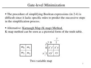
3-1 Introduction Gate-level minimization refers to the design task of finding an optimal gate-level implementation of Boolean functions describing a digital circuit.
3-2 The Map Method • The complexity of the digital logic gates • The complexity of the algebraic expression • Logic minimization • Algebraic approaches: lack specific rules • The Karnaugh map • A simple straight forward procedure • A pictorial form of a truth table • Applicable if the # of variables < 7 • A diagram made up of squares • Each square represents one minterm
Review of Boolean Function • Boolean function • Sum of minterms • Sum of products (or product of sum) in the simplest form • A minimum number of terms • A minimum number of literals • The simplified expression may not be unique
Two-Variable Map Figure 3.1 Two-variable Map Figure 3.2 Representation of functions in the map • A two-variable map • Four minterms • x' = row 0; x = row 1 • y' = column 0; y = column 1 • A truth table in square diagram • Fig. 3.2(a): xy = m3 • Fig. 3.2(b): x+y = x'y+xy' +xy = m1+m2+m3
A Three-variable Map Figure 3.3 Three-variable Map • A three-variable map • Eight minterms • The Gray code sequence • Any two adjacent squares in the map differ by only on variable • Primed in one square and unprimed in the other • e.g., m5 and m7 can be simplified • m5+ m7 = xy'z + xyz = xz (y'+y) = xz
A Three-variable Map • m0and m2(m4 and m6) are adjacent • m0+ m2= x'y'z' + x'yz' = x'z' (y'+y) = x'z' • m4+ m6= xy'z' + xyz' = xz' (y'+y) = xz'
Example 3.1 Figure 3.4 Map for Example 3.1, F(x, y, z) = Σ(2, 3, 4, 5) = x'y + xy' • Example 3.1: simplify the Boolean function F(x, y, z) = S(2, 3, 4, 5) • F(x, y, z) = S(2, 3, 4, 5) = x'y + xy'
Example 3.2 Figure 3.5 Map for Example 3-2; F(x, y, z) = Σ(3, 4, 6, 7) = yz + xz' • Example 3.2: simplify F(x, y, z) = S(3, 4, 6, 7) • F(x, y, z) = S(3, 4, 6, 7) = yz+ xz'
Four adjacent Squares Figure 3.3 Three-variable Map • Consider four adjacent squares • 2, 4, and 8 squares • m0+m2+m4+m6 = x'y'z'+x'yz'+xy'z'+xyz' = x'z'(y'+y) +xz'(y'+y) = x'z' + xz‘ = z' • m1+m3+m5+m7 = x'y'z+x'yz+xy'z+xyz =x'z(y'+y) + xz(y'+y) =x'z + xz = z
Example 3.3 Figure 3.6 Map for Example 3-3, F(x, y, z) = Σ(0, 2, 4, 5, 6) = z' +xy' • Example 3.3: simplify F(x, y, z) = S(0, 2, 4, 5, 6) • F(x, y, z)= S(0, 2, 4, 5, 6) = z'+ xy'
Example 3.4 Figure 3.7 Map for Example 3.4, A'C + A'B + AB'C + BC = C + A'B • Example 3.4: let F = A'C + A'B + AB'C + BC • Express it in sum of minterms. • Find the minimal sum of products expression. Ans: F(A, B, C) = S(1, 2, 3, 5, 7) = C + A'B
3.3 Four-Variable Map Figure 3.8 Four-variable Map • The map • 16 minterms • Combinations of 2, 4, 8, and 16 adjacent squares
Example 3.5 • F = y'+w'z'+xz' Figure 3.9 Map for Example 3-5; F(w, x, y, z) = Σ(0, 1, 2, 4, 5, 6, 8, 9, 12, 13, 14) = y' + w' z' +xz' Example 3.5: simplify F(w, x, y, z) = S(0, 1, 2, 4, 5, 6, 8, 9, 12, 13, 14)
Example 3.6 Figure 3.9 Map for Example 3-6; ABC + BCD + ABCD + ABC= BD + BC +ACD Example 3-6: simplify F = ABC + BCD + ABCD + ABC
Prime Implicants • Prime Implicants • All the minterms are covered. • Minimize the number of terms. • A prime implicant: a product term obtained by combining the maximum possible number of adjacent squares (combining all possible maximum numbers of squares). • Essential P.I.: a minterm is covered by only one prime implicant. • The essential P.I. must be included.
Prime Implicants Figure 3.11 Simplification Using Prime Implicants • Consider F(A, B, C, D) = Σ(0, 2, 3, 5, 7, 8, 9, 10, 11, 13, 15) • The simplified expression may not be unique • F = BD+B'D'+CD+AD = BD+B'D'+CD+AB' = BD+B'D'+B'C+AD = BD+B'D'+B'C+AB'
3.4 Five-Variable Map Figure 3.12 Five-variable Map • Map for more than four variables becomes complicated • Five-variable map: two four-variable map (one on the top of the other).
Table 3.1 shows the relationship between the number of adjacent squares and the number of literals in the term.
Example 3.7 F = A'B'E'+BD'E+ACE Example 3.7: simplify F = S(0, 2, 4, 6, 9, 13, 21, 23, 25, 29, 31)
Example 3.7 (cont.) Figure 3.13 Map for Example 3.7, F = A'B'E'+BD'E+ACE Another Map for Example 3-7
3-5 Product of Sums Simplification CD 00 01 11 10 AB 00 01 11 10 • Approach #1 • Simplified F' in the form of sum of products • Apply DeMorgan's theorem F = (F')' • F': sum of products → F: product of sums • Approach #2: duality • Combinations of maxterms (it was minterms) • M0M1 = (A+B+C+D)(A+B+C+D') = (A+B+C)+(DD') = A+B+C
Example 3.8 • F(A, B, C, D)= S(0, 1, 2, 5, 8, 9, 10) = B'D'+B'C'+A'C'D • F' = AB+CD+BD' • Apply DeMorgan's theorem; F=(A'+B')(C'+D')(B'+D) • Or think in terms of maxterms Figure 3.14 Map for Example 3.8, F(A, B, C, D)=S(0, 1, 2, 5, 8, 9, 10) = B'D'+B'C'+A'C'D • Example 3.8: simplify F = S(0, 1, 2, 5, 8, 9, 10) into (a) sum-of-products form, and (b) product-of-sums form:
Example 3.8 (cont.) Product-of sums form Sum-of products form Figure 3.15 Gate Implementation of the Function of Example 3.8 Gate implementation of the function of Example 3.8
Sum-of-Minterm Procedure • Consider the function defined in Table 3.2. • In sum-of-minterm: • In sum-of-maxterm: • Taking the complement of F
Sum-of-Minterm Procedure ' Figure 3.16 Map for the function of Table 3.2 • Consider the function defined in Table 3.2. • Combine the 1’s: • Combine the 0’s :
3-6 Don't-Care Conditions • The value of a function is not specified for certain combinations of variables • BCD; 1010-1111: don't care • The don't-care conditions can be utilized in logic minimization • Can be implemented as 0 or 1 • Example 3.9: simplify F(w, x, y, z) = S(1, 3, 7, 11, 15) which has the don't-care conditions d(w, x, y, z) = S(0, 2, 5).
Example 3.9 (cont.) Figure 3.17 Example with don't-care Conditions • F = yz + w'x'; F = yz + w'z • F = S(0, 1, 2, 3, 7, 11, 15) ; F = S(1, 3, 5, 7, 11, 15) • Either expression is acceptable
3-7 NAND and NOR Implementation Figure 3.18 Logic Operations with NAND Gates • NAND gate is a universal gate • Can implement any digital system
NAND Gate Figure 3.19 Two Graphic Symbols for NAND Gate Two graphic symbols for a NAND gate
Two-level Implementation Figure 3.20 Three ways to implement F = AB + CD • Two-level logic • NAND-NAND = sum of products • Example: F = AB+CD • F = ((AB)' (CD)' )' =AB+CD
Example 3.10 Figure 3.21 Solution to Example 3-10 Example 3-10: implement F(x, y, z)=
Procedure with Two Levels NAND • The procedure • Simplified in the form of sum of products; • A NAND gate for each product term; the inputs to each NAND gate are the literals of the term (the first level); • A single NAND gate for the second sum term(the second level); • A term with a single literal requires an inverter in the first level.
Multilevel NAND Circuits Figure 3.22 Implementing F = A(CD + B) + BC • Boolean function implementation • AND-OR logic → NAND-NAND logic • AND → AND + inverter • OR: inverter + OR = NAND • For every bubble that is not compensated by another small circle along the same line, insert an inverter.
NAND Implementation Figure 3.23 Implementing F = (AB +AB)(C+ D)
NOR Implementation Figure 3.24 Logic Operation with NOR Gates NOR function is the dual of NAND function. The NOR gate is also universal.
Two Graphic Symbols for a NOR Gate Figure 3.25 Two Graphic Symbols for NOR Gate Example: F = (A + B)(C + D)E Figure 3.26 Implementing F = (A + B)(C + D)E
Example Example: F = (AB +AB)(C + D) Figure 3.27 Implementing F = (AB +AB)(C + D) with NOR gates
3-8 Other Two-level Implementations ( AND-OR-INVERT function OR-AND-INVERT function Figure 3.28 Wired Logic • Wired logic • A wire connection between the outputs of two gates • Open-collector TTL NAND gates: wired-AND logic • The NOR output of ECL gates: wired-OR logic
Non-degenerate Forms • 16 possible combinations of two-level forms • Eight of them: degenerate forms = a single operation • AND-AND, AND-NAND, OR-OR, OR-NOR, NAND-OR, NAND-NOR, NOR-AND, NOR-NAND. • The eight non-degenerate forms • AND-OR, OR-AND, NAND-NAND, NOR-NOR, NOR-OR, NAND-AND, OR-NAND, AND-NOR. • AND-OR and NAND-NAND = sum of products. • OR-AND and NOR-NOR = product of sums. • NOR-OR, NAND-AND, OR-NAND, AND-NOR = ?
AND-OR-Invert Implementation Figure 3.29 AND-OR-INVERT circuits, F = (AB +CD +E) • AND-OR-INVERT (AOI) Implementation • NAND-AND = AND-NOR = AOI • F = (AB+CD+E)' • F' = AB+CD+E (sum of products)
OR-AND-Invert Implementation • Figure 3.30 OR-AND-INVERT circuits, F = ((A+B)(C+D)E)' • OR-AND-INVERT (OAI) Implementation • OR-NAND = NOR-OR = OAI • F = ((A+B)(C+D)E)' • F' = (A+B)(C+D)E (product of sums)
Tabular Summary and Examples • Example 3-11: F = x'y'z'+xyz' • F' = x'y+xy'+z (F': sum of products) • F = (x'y+xy'+z)' (F: AOI implementation) • F = x'y'z' + xyz' (F: sum of products) • F' = (x+y+z)(x'+y'+z) (F': product of sums) • F = ((x+y+z)(x'+y'+z))' (F: OAI)
3-9 Exclusive-OR Function • Exclusive-OR (XOR) • xÅy = xy'+x'y • Exclusive-NOR (XNOR) • (xÅy)' = xy + x'y' • Some identities • xÅ0 = x • xÅ1 = x' • xÅx = 0 • xÅx' = 1 • xÅy' = (xÅy)' • x'Åy = (xÅy)' • Commutative and associative • AÅB = BÅA • (AÅB) ÅC = AÅ (BÅC) = AÅBÅC
Exclusive-OR Implementations Figure 3.32 Exclusive-OR Implementations • Implementations • (x'+y')x + (x'+y')y = xy'+x'y = xÅy
Odd Function Figure 3.33 Map for a Three-variable Exclusive-OR Function • AÅBÅC = (AB'+A'B)C' +(AB+A'B')C = AB'C'+A'BC'+ABC+A'B'C = S(1, 2, 4, 7) • XOR is a odd function → an odd number of 1's, then F = 1. • XNOR is a even function → an even number of 1's, then F = 1.
XOR and XNOR Figure 3.34 Logic Diagram of Odd and Even Functions Logic diagram of odd and even functions
Four-variable Exclusive-OR function Figure 3.35 Map for a Four-variable Exclusive-OR Function • Four-variable Exclusive-OR function • AÅBÅCÅD = (AB'+A'B)Å(CD'+C'D) = (AB'+A'B)(CD+C'D')+(AB+A'B')(CD'+C'D)