
Efficient IP Addressing System for Network Routing
Learn about the evolution of IP addressing from classful systems to CIDR, subnetting, and flexibility in subnet assignment for optimal network management.

Efficient IP Addressing System for Network Routing
E N D
Presentation Transcript
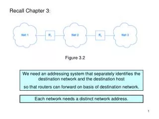
Recall Chapter 3: Figure 3.2 We need an addressing system that separately identifies the destination network and the destination host so that routers can forward on basis of destination network. Each network needs a distinct network address.
Recall Chapter 4: every physical network has to have its own unique IPv4 network address (class A, B, or C) Figure 4.1 The classful system is rigid and wasteful of the IP address space. With the advent of Local Area Networks and growth of the Internet, it became clear that the IPv4 address space would “soon” become exhausted. Efforts to utilize the IPv4 address space more efficiently and delay exhaustion: ► 1987 subnetting (chapter 9A) ► 1993 supernetting (chapter 9B) ► 2000 network address translation (chapter 19)
Chapter 9 – Classless and Subnet Address Extensions (CIDR) 9.3 Minimizing Network Numbers We have been assuming that every physical network had its own class A, B, or C IP network prefix. UAB has class B network address 138.26.0.0 But there is clearly more than one physical network on campus! 9.5 Subnet Addressing This became a required part of IP in 1987. Individual sites have the freedom to modify addresses and routes as long as the modifications remain invisible to other sites. A site can choose to use IP addresses in unusual ways internally as long as: ► all hosts and routers at the site agree to honor the site’s addressing scheme; ► other sites on the Internet can treat addresses as a network prefix and a host suffix.
9.5 Subnet Addressing - continued Example: Site with class B address 128.10.0.0 has two physical networks - subnets Figure 9.2 Only router R knows that there are multiple physical networks at the site and how to forward traffic among them; all other routers in the Internet forward traffic as if there were a single physical network at the site.
9.5 Subnet Addressing - continued In this example the local site has chosen to use the third octet of the address to distinguish between the two networks. “Subnetting on the basis of the 3rd octet”
9.5 Subnet Addressing – continued Relationship to original “classful” addressing system Original classful IP addressing With subnet addressing subnet Figure 9.3 Hierarchical routing: Routers in other autonomous systems use only the Internet part; Routers within this autonomous system also use the additional octet; Final delivery to host also uses the remaining octet.
9.6 Flexibility in Subnet Assignment Subnetting on the basis of the third octet is not the only possibility. Consider this intranet: Figure 9.4 Need 5 subnets - How could subnet addressing be performed?
9.6 Flexibility in Subnet Assignment – continued The number of bits allocated to the subnet can be chosen to fit the situation. Slice up the pie for a class-B address:
Figure 9.4 In this example, allocating 3 bits would allow 6 subnets (23 – 2), each with up to 8190 (213 – 2) hosts. ( -2 because we do not assign all-zeros or all-1s to hosts or subnets)
9.8 Implementation of Subnets with Masks The division of the 32-bit IP address for subnetting is controlled by the 32-bit subnet mask or address mask For example, subnetting on the basis of the third octet is represented by 11111111 11111111 11111111 00000000 Network + subnet part Host part We use dotted decimal notation to represent this as 255 . 255 . 255 . 0 To extract the (network + subnet) part of an IP destination address (as needed for routing within intranet): <destination IP address> .AND. <subnet mask>
9.11 The Subnet Forwarding Algorithm Before subnetting, the rows of the routing table contained duples <destination network address> <next hop> We extracted the destination network address from the 32-bit datagram destination address by looking at the first 1, 2, or 3 bits, to identify if the destination host was connected to a class A, B, or C network. With subnetting it is no longer possible for internal routers to deduce the destination network address on the basis of the datagram destination address alone. We have to expand our routing table rows to triples <address mask> <destination network address> <next hop> and revise the forwarding algorithm used in the intranet.
9.12 A Unified Forwarding Algorithm Recall the Chapter 7 forwarding algorithm: Before subnetting we could determine N from destination IP address alone Figure 7.3 This algorithm has to be modified to account for subnetting.
9.12 A Unified Forwarding Algorithm – continued This also needs to be ANDed with the address mask New step Figure 9.7 Only the internal routers have to be modified, since subnetting is invisible to outsiders.
9.12 A Unified Forwarding Algorithm Recall the Chapter 7 forwarding algorithm: Figure 7.3 What happened to these special cases?
9.12 A Unified Forwarding Algorithm – continued What happened to the special cases in figure 7.3? Host-specific route: use address mask 255.255.255.255 Default route: use address mask 0 . 0 . 0 . 0 with destination network address 0 . 0 . 0 . 0 table row will be <address mask> <destination network address> <next hop> 0 . 0 . 0 . 0 0 . 0 . 0 . 0 next hop for default route (because any ID ANDed with 0 . 0 . 0 . 0 gives 0 . 0 . 0 . 0) Default route must be last row in forwarding table.
Class B address 138.26.0.0 All subnet masks 255.255.255.0 .254 138.26.1.0 .253 .252 .1 .254 138.26.2.0 138.26.3.0 .252 .253 Figure 9.4
9.13 Maintenance of Subnet Masks Subnet masks are assigned by the network administrator.
9.14 Broadcasting to Subnets Recall special forms of IP address from chapter 4: Figure 4.4 Following this, we interpret an IP address <network part> <subnet part> 111…11 as indicating broadcast to all hosts on <subnet>
9.15 Anonymous Point-to-Point Networks A typical situation for a router in a wide-area network is that once an exit interface has been chosen, there is only one possible destination. In this situation we don’t need to waste an IP network prefix and don’t need to ARP.
9.15 Anonymous Point-to-Point Networks - continued Figure 9.8(b) routing table in R1 There is no need for a “next hop” – the exit interface is sufficient.
Chapter 19 – Private Network Connection (NAT, VPN) 19.6 Network Address Translation Like subnetting, NAT was motivated by a shortage of IPv4 addresses NAT provides IP-level access between hosts at a site and the rest of the Internet, without requiring each host at the site to have a globally-valid IP address (can use private, non-unique addresses eg. 192.168.1.1 ) Allows an internal host to access service on an external computer. The site must have a single router, with at least one globally-valid IP address, G, connecting to the Internet. This router runs the NAT software. All datagrams pass through the “NAT box” on their way to or from the Internet.
NAT Outgoing datagrams: NAT replaces the (private) source address with G
NAT Reply datagram will arrive at G - how does router/NAT know which internal host should receive the datagram? NAT maintains a translation table that it uses to perform the mapping. Entry in table: IP address of the external server, IP address of internal client NAT converts destination address G to private address 192.168.1.1 and forwards the datagram.
19.7 NAT Translation Table Creation How is the translation table constructed? 3 possibilities: ► Manual Initialization ► Outgoing Datagrams this is the “classic” method – when datagram arrives at the internal NAT interface, the router records the (internal) source address and the (external) destination address. This method does not allow contact to be initiated from outside (may not be a bad thing – security) ► Incoming Name Lookups table is built as a side-effect of handling incoming DNS lookups (possible only if organization is running a DNS server and is willing to have external access).
19.7 NAT Translation Table Creation – continued “Outgoing datagram” method popular among ISPs Figure 19.4
19.8 Multi-Address NAT Problem: What if two internal hosts are accessing the same external server at the same time? Translation table, with entries IP address of the external server, IP address of internal client will be ambiguous. First idea: NAT box has a set of globally-valid IP addresses, G1 .. GK Up to K internal clients can access the same server at the same time.
19.9 Port-Mapped NAT Network Address and Port Translation (NAPT) is a better solution. Outgoing datagrams: NAPT substitutes both source IP address and source port. Inside client Outside server Figure 19.5 - reduced
19.9 Port-Mapped NAT - continued Since ports are 16-bit quantities, NAPT allows up to 216 internal client to access the same external server at the same time. In our implementation in the lab, the NAT box does not substitute a source port unless two internal clients accidentally choose the same random client port number.
Transport NAPT gets router involved in layer 4! (looking inside “data” in IP datagram, not just header)
19.10 Interaction between NAPT and ICMP NAPT uses the port number to identify the client. ICMP is layer 3, so does not have a port number. So how can PING, or ICMP error messages, work through a NAT box?
19.10 Interaction between NAPT and ICMP– continued PING What does the NAT box do?
19.10 Interaction between NAT and ICMP– continued Format for echo request/ echo reply: Although there is no port number that can be used, there is the IDENTIFIER field. This contains a 16-bit number chosen randomly by the requestor. RFC 2663 states that this is used by NAT, in place of a port number, to route the echo reply back to the requestor over the intranet.
19.10 Interaction between NAT and ICMP – continued What about ICMP error messages, such as “destination unreachable”? Situation with NO NAPT Outer IP Datagram Inner IP Datagram
19.10 Interaction between NAT and ICMP– continued IP: source = G, dest = W TCP: source port = y, dest = 80 IP: source = S, dest = W TCP: source port = x, dest =80 G,W,y,80↔S,W,x,80 IP: source = R, dest = G ICMP type 3 Inner datagram IP: source = G, dest = W TCP: source port = y, dest = 80 IP: source = R, dest = G ICMP, Not TCP! IP: source = R, dest = S ICMP type 3 Inner datagram IP: source = S, dest = W TCP: source port = x, dest = 80 Have this! Need this!
19.10 Interaction between NAT and ICMP– continued Inner Datagram NAPT has to “drill down” into inner datagram to retrieve source port y, and original destination W, then do table lookup to find that the ICMP message should be forwarded to S.
19.10 Interaction between NAT and ICMP– continued Before forwarding the ICMP “destination unreachable” message to the sender of the original datagram, NAT must translate the addresses in the ICMP message so that they are exactly the same as in the original datagram. Then recompute the checksum in the ICMP header, then recompute the checksum in the outer IP datagram header.
19.10 Interaction between NAT and ICMP – continued To provide a meaningful ICMP “destination unreachable” to the original sender of the datagram, the NAT box must: ► Translate the source address in the “inner” datagram ► Translate the source port in the “inner” datagram ► Recompute the header checksum in the “inner” datagram ► Recompute the ICMP header checksum ► translate the destination IP address in the “outer” header ► Recompute the header checksum in the “outer” header.
19.11 Interaction between NAT and Applications Applications cause problems if they send IP addresses or protocol ports as data. e.g. FTP (active mode): Frame from Ethereal trace captur2a.ftp Frame 25 Ethernet II Internet Protocol Protocol: TCP (0x06) Header checksum: 0xb213 (correct) Source: 192.168.1.1 (FTP Client) Destination: 192.168.1.2 (FTP Server) Transmission Control Protocol Source port: 1388 Destination port: ftp (21) File Transfer Protocol (FTP) Request: PORT Request Arg: 192,168,1,1,5,109 [Port information transmitted in ASCII]
19.11 Interaction between NAT and Applications - continued NAT Active mode FTP does not work with NAT for internal client, external server,
FTP message Transport Fixing FTP in active mode would require the router to “drill down” all the way to the FTP message.
19.11 Interaction between NAT and Applications - continued NAT FTP in passive does work between internal client and external server (confirmed by RFC 2663)
19.12 NAT in the Presence of Fragmentation NAPT cannot work with fragmented datagrams, since only the first fragment will contain the TCP or UDP header, with the port numbers.
19.13 Conceptual Address Domains “We have described NAT as a technology that can be used to connect a private network to the global internet. In fact, NAT can be used to connect any two address domains.” This leads to multiple levels of NAT.
19.14 Slirp and iptables iptables supports packet rewriting and firewalling. We use iptables in lab session #5 to construct packet filters. NAT or NAPT can be constructed using iptables rules.