DATA ACQUISITION
DATA ACQUISITION. Today’s Topics Define DAQ and DAQ systems Signals (digital and analogue types) Transducers Signal Conditioning - Importance of grounding

DATA ACQUISITION
E N D
Presentation Transcript
DATA ACQUISITION Today’s Topics • Define DAQ and DAQ systems • Signals (digital and analogue types) • Transducers • Signal Conditioning - Importance of grounding - Differential, Referenced and nonferenced single ended signals- A to D conversion considerations (resolution, device and signal range, sampling rate) • In Class Example – Signal input range calculation • Assign homework and begin in class
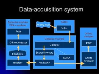
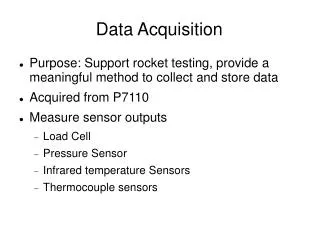
DATA ACQUISITION - DEFINED • DATA ACQUISITION(DAQ) is the measurement or generation of physical signals. • DAQ systems typically consists of five elements: 1. Signals 2. Transducers 3. Signal-conditioning hardware 4. DAQ device or module 5. Application software
SIGNALS • Signals are physical quantities that are functions of an independent variable (such as time) and contain information about a natural phenomenon • Two types of signals may be defined; digital and analogue. - Digital signals provide information regarding the voltage state (typically hi or low) and/or the rate of change of these states - An analogue signal typically provides voltage level, shape or frequency content information.
Signal types and classes • Two types of Digital signals: - on-off - pulse train, • Three types of analogue - DC - AC - frequency domain • Total of 5 signal classes • ADC - analogue to digital converter, which converts the analogue signal into a digital signal which can be read by a computer • DAC - digital to analogue converter, which converts a digital signal to an analogue signal • TTL - transistor to transistor logic
TRANSDUCERS • A transducer is a device which converts a physical phenomenon into a measurable electrical signal.
SIGNAL CONDITIONING Transducer output is usually computer ready and must be conditioned, either using hardware or software:Transducer excitation – use of an external voltage or current to excite the transducer (ex: strain gauges) • Linearization – creation of a linear relationship between the transducer output and the physical phenomenon being measured • Isolation - isolation of the transducer signal from the computer and other transducers • Filtering - conditioning of a signal to reduce unwanted components (i.e., noise, high or low frequency components, etc.) • Amplification - increace of the output signal of the transducer to increace accuracy and signal to noise ratio
LABVIEW SCXI SIGNAL CONDITIONING • SCXI (Signal Conditioning Xtensions for Instrumentation) is a hardware device designed to condition low level signals in a noisy environment within an external chassis located near the sensor. • Some signal conditioning, such as linearization and filtering, can often be performed using software, and LabVIEW provides several VIs for these purposes.
SIGNAL GROUNDING • Two types of signal sources- grounded: signals which are referenced to a system ground ex:110V outlets, signal generators, power supplies - floating: signals which are not connected to an absolute reference ex: battery powered sources, thermocouples transformers
NOTES ON MEASUREMENT SYSTEMS A measurement system can be placed into on of three categories: • Differential: - Neither the positive or negative terminal of the source or transducer is connected to ground.- The system only measures the difference between the terminals, and rejects other voltages in the system. - It is therefore preferred. • Referenced single ended (RSE)- Measures a signal with respect to the system ground.- Use if more channels are required. • Non-referenced single ended (NRSE)- all measurements are made with respect to a common reference other than the system ground.
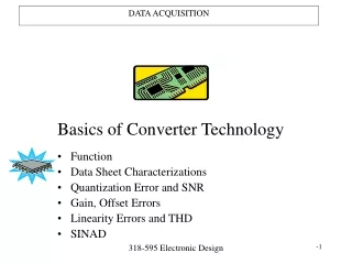
ANALOGUE TO DIGITALCONVERSION CONSIDERATIONS The quality of the analogue to digital conversion is dependent on the following four parameters: • Resolution • Device range • Signal input range • Sampling rate These will be set using hardware (board switches) or software (Measurement and Automation Explorer in Labview)
1. RESOLUTION • Resolution: The number of bits used to represent the analogue signal 16-bit The above example shows the difference between 3 (23 =8 divisions) and 16 bit (216 = 65,536 divisions) resolution
2. DEVICE RANGE • device range: minimum and maximum analogue signal levels that the ADC can convert. • The device range should be matched to the range of the analogue input signal to best take advantage of the available resolution!
2. DEVICE RANGE (cont’s) • Example: If a 3-bit ADC (having 8 divisions) is used over a range of 0 to 10 volts, voltage changes of 1.25V can be measured.However, if the range is increased to -10 to 10V, then the smallest voltage change which can be measured rises to 2.5V
3. SIGNAL INPUT RANGE • signal input range: the maximum and minimum value of the signal being measured. • The closer the signal input range is to the incoming analogue signal max and min, the more digital divisions will be available to the ADC to represent the signal
SMALLEST DETECTABLE VOLTAGE CHANGE • Determined by the resolution and range of a DAQ device and the signal input range. • This change in voltage represents 1 least significant bit (LSB) of the digital value and is often called the code width. • This smallest code width, Vcw is calculated as follows (Where the resolution is given in bits) • Example: a 12 bit DAQ device with a 0 to 10V range can detect a 2.4 mV change. • Unipolar signals range from 0 to a positive value • bipolar signals range from a negative to a positive value.
4. SAMPLING RATE • sampling rate: the rate at which the DAQ device samples an incoming analogue signal • Determines how often an analogue to digital conversion takes place. • Computing the proper sampling rate requires knowledge of the max frequency of the incoming signal and the accuracy required for digital representation. • In general, a fast sampling rate acquires more points per unit time and results in a better representation of the incoming signal.