Download
1 / 45
450 likes | 548 Vues
Explore the essential design tools and modelling techniques for composite materials, covering selection, analysis, failure criteria, and durability issues. Learn how advanced software like CoDA revolutionizes composite structure design.

E N D
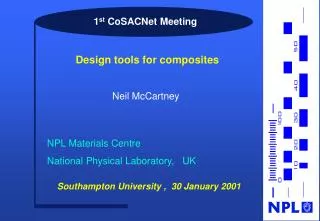
1st CoSACNet Meeting Design tools for composites Neil McCartney NPL Materials Centre National Physical Laboratory, UK Southampton University , 30 January 2001
Definition of design ? • Selection of materials, geometry, loading modes and limits so that products meet specified performance criteria e.g. • deflections within specification • failure loads in excess of maximum expected load during service • avoidance of microstructural damage ( ply cracks / delaminations ) • lifetimes ( cycles / time ) in excess of specification • Design is quantitative and based on mathematical models that adequately represent behaviour • semi-empirical / phenomenological relationships • analytical formulae ( fromHooke’s law to complex analyses ) • finite element or boundary element analysis
Modelling issues for composites • Reliable design procedures will be based on physical modelling • The availability of high performance computers will revolutionise the design of composite structures • Realistic complex models can be used for design of materials (Virtual Testing) and components • Models must be thoroughly validated and incorporated into easy-to-use design procedures • Life prediction, durability are exceedingly complex phenomena that are very difficult to model physically • Phenomenological approaches can be useful but are not usually reliable – e.g. failure criteria for composites
Conventional failure criteria Tsai - Wu (1971) • phenomenological in nature - no physics ! • based on invariance requirements • applied to stress states for composite structures where no damage has been allowed for • not easily applied to environmentally or fatigue damaged composites Physically based models are needed !
Design issues for composites • Materials design • Fibre / matrix / volume fraction selection for UD laminates • Orientation / thickness selection for plies in a laminate • Prediction of elastic constants • Prediction of expansion coefficients ( thermal / moisture ) • Types of loading • In-plane biaxial - through-thickness - shear • Out-of-plane bending ( anticlastic bending ) • Damage growth and property degradation • Ply cracking – delamination – fibre fracture – interface debonding • Strength predictions • Durability issues – fatigue – environmental exposure • Delivery of design methods to users ( Software – Web )
Delivering design tools to users Commercial systems LAP and CoDA UK Composite Design Toolset ( DERA, AEAT, NPL, SER Systems Ltd ) Web-based design tools – E-mail communication Smart design manuals
A commercially supported package CoDA for Component and Composite Design Analysis Version 3 Graham D Sims and Bill Broughton NPL Materials Centre National Physical Laboratory, UK CoDA
What does CoDA do ? • CoDA has four independent, but integrated, modules that have been validated experimentally • Panels, Beams, Laminates, Materials Synthesiser • Pre-preg laminates, chopped strand mat, sandwich panels • Implementation of failure criteria • CoDA can be used to undertake preliminary analysis of sub-components with Plate or Beam geometries • CoDA can also synthesise the properties of composite materials, laminates and sandwich structures, which can be used in a seamless manner within the design modules CoDA
UK Composite Design Toolset • A collaboration between DERA, UKAEA & NPL • Integrated toolbox comprising modules that can exchange data & results • PC008A/15A – DERA – Micromechanics, LPT, 2D/3D • GENLAM – DERA – Non-linear LPT – thermal stresses – scissoring • CCSM – Cambridge, IC, DERA – Micromechanics + LPT – unnotched & notched failure • PREDICT – NPL – progressive damage modelling in laminates • LAMFAIL – UMIST, DERA progressive damage with empirical model – nonlinear scissoring – complex load histories • A global data base of materials properties – links to other systems
PREDICT - Design objectives • Predict properties of UD composites from properties of fibre and matrix • Predict in-plane properties of general symmetric laminates • Predict initial formation of fully developed ply cracks in a general symmetric laminates subject to general in-plane loading and thermal residual stresses ( in fatigue loading designers will want to avoid damage ) • Predict progressive degradation of thermo-elastic constants as a function of applied stress or strain ( strain softening rules needed for FEA analyses ) • Predict effects on damage resistance of varying orientations and thicknesses of plies in a laminate • Predict effects of temperature changes on ply crack formation ( investigate thermal cracking during manufacture, or cooling )
Designing composites from fibre and matrix level Predicting ply properties – validation Predicting laminate properties Delaying damage formation during loading PREDICT
Quasi - isotropic laminates Ply geometry and location of ply cracks Ply 1 Ply 2 Ply3 Ply 4 2L 0o 90o - 45o 45o 45o - 45o 90o 0o
45o - 45o 90o 0o Plycrack
GRP : Predicted from fibre/matrix properties Experimental data : Lodiero & Broughton, NPL, 2000
Stress - strain relations for damaged laminate w is a label denoting the presence of some form of damage in the laminate defined by a set of other parameters Same form as those for an undamaged laminate Validity confirmed by accurate stress analysis
Degradation of properties of laminates Damage parameter : Thermo-elastic constants for damaged laminates : k, k’ and k1 are easily calculated using CLT
Continuum damage mechanics (CDM) Stress - strain relation e = Sswhere Damage parameters d1, d2and d3 are such that
Face view of crack growth using continuum model Master curve for ply cracking s s s s
Design limit is derived for long cracks • Design limit is exact if growth is stable • Design limit is a lower bound if growth is unstable • Predictions are pessimistic • Designs will be safe Unstable growth Design limit Stable growth
Criteria for ply crack formation Ply crack initiation criterion : s0 is value of s at ply crack closure Criterion for progressive discrete ply crack formation :
Progressive cracking methodology Potential cracking sites Ply crack locations Potential cracking sites are evenly spaced Ply cracks are non-uniformly spaced
Master curve for triaxial loading Key features : s - s0 • Damage initiation stress • Gradient of unloading line • Enclosed area • = 0 si- s0 Apply directly to other stress and temperature states for which g = 0 : Area G(w) Inelastic strain e(w) - e 0
A popular approach of damage mechanics Degraded properties modelled semi-empirically Classical laminate analysis Homogeneous damaged ply in laminate Homogenised Cracked laminate
Approach of NPL model Homogenised Cracked laminate Homogeneous damaged ply in laminate Cracked laminate
Out - of - plane bending • Non-symmetrical laminates • Through-thickness thermal gradients • Major problem is dealing with anti-clastic bending • Model already exists for ply cracks subject to plane strain bending Anti-clastic bending of UD ply
Plane strain bending of cracked [ 0 / 90 / 0 / 90 / 0 ] laminate M M y 0 0 i = 1 i = 2 90 0 90 i = N+1 0 x - Work in progress to predict ply crack formation -
GRP laminate Ply crack 90o ply 0o ply 0o ply 90o ply 0o ply
Modelling laminate failure Physical modelling of damage modes Cross-ply laminates subject to biaxial loading Prediction of failure strain and strength
Modelling failure of cross-ply laminates • Effects of ply cracking alone on laminate properties are well understood • Ply cracking affects thermo-elastic properties (strain softening) but we need to address laminate failure issues • Tensile failure is determined principally by fibre fracture • Statistical nature of fibre failure must be included • Predicting the failure of cross-ply laminates is the first step 0o 90o 0o Biaxial loading Thermal stresses Multiple plies
Modelling failure of cross-ply laminates 0o 90o 0o Static failure of fibres • fibre/matrix debonding • frictional contact • shear yielding Biaxial loading Thermal stresses Fibre matrix cell Biaxial stresses Thermal stresses
L - b is length of debond zone Mechanical behaviour of fibre / matrix cell Could substitute any other model for which a look-up table can be constructed
Monte Carlo model for progressive failure in 0o plies Repeated runs of a simulation to determine the statistical variability of performance Parameters : M, N, L Element lengthd
Critical fibre stress or strain ? • In fibre tests performance of fibre in tension can be characterised by : • axial fibre stress at failure • axial strain at failuresf = Efef • In a composite fibre subject to triaxial loading • there are both loading & Poisson ratio effects on axial fibre strain • Assume fibre strength in a composite is governed by axial fibre failure strain • consistent with concept of fibre axial strain controlling the stability of fibre defects initiating tensile failure
Failure Failure The effect of fibre fracture on properties Failure CFRP (Vf = 0.6)
Virtual Testing • Virtual testing is defined as the combination of high quality models, high performance computing and a user - friendly interface • Will replicate many aspects of physical mechanical testing so that engineers do not need to learn a new vocabulary • Will allow material properties to be derived from more fundamental properties, leading to inventive materials design • It will be more than just a simulation, because extensive validation and testing will have taken place, resulting in a reliable replacement for some physical testing
Virtual testing of composites over the Internet Web site address http://materials.npl.co.uk/
Virtual testing : Composite laminates • Developed at NPL, the Internet based system enables a materials designer to ‘create’ an entirely new material and to test it The system simulates the damage caused by cracking as load increases and predicts the subsequent degrading of material properties Image taken from NPL Internet Laminate Damage Simulation
Composite Laminate Testing • The user can generate design data for damaged composite laminates Results taken from NPL Internet version of Laminate Damage Simulation
Conclusions • Reliable design methods for composite materials will be based on physical models of behaviour. Key to reliability is rigorous validation of design methods • Physical models are complex in nature and not usually amenable to simple design rules ( sometimes there is no alternative ) • Damage models have good potential for application in construction sector ( e.g. bridge strengthening with CFRP ) • The implementation of physically based design methods in design offices will usually involve the use of computer based techniques : • Specific software packages – LAP, CoDA, Toolset • Web-based access to specific design packages, NPL demonstrator • Web-based access to distributed software – networking ? • Integration of design, optimisation, prototype and production simulation in virtual manufacturing