Maps: An Overview
Maps: An Overview. By Monica Spicker 2012. Objectives. Identify different types of maps Identify elements of maps Use scale ratio and scale bar to determine distance Identify terrain features from contours Determine elevation Match map features to real features in the field.

Maps: An Overview
E N D
Presentation Transcript
Maps: An Overview By Monica Spicker 2012 B M O C
Objectives • Identify different types of maps • Identify elements of maps • Use scale ratio and scale bar to determine distance • Identify terrain features from contours • Determine elevation • Match map features to real features in the field. • Identify hazardous slopes via contours by aspect, shape and steepness. B M O C
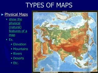
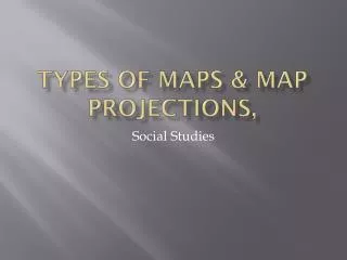
Types of Maps • Planimetric • Flat surface – no geographic features • Road maps, ownership maps, tourist maps. • Topographic • Terrain represented via contour lines • Other geographic features such as rivers, seasonal creeks, permanent snowfields, vegetation, etc. B M O C
Elements of Maps • North • True • Magnetic • Grid • Scale • Scale bar • Scale ratio • 1 ruler unit on map = RF ruler units on the ground • 1: 24000 means 1 map inch = 24000 ground inches or 1 map cm = 24000 ground cm. • Need to convert ratio ruler units to ground units or ground units to map inches to use correctly! B M O C
Elements of Maps • Legend • Not all symbols mean the same thing • Certain cultural biases • Grid systems • Alphanumeric • Public Land Survey System (PLSS or “legals”) • Geographic (Latitude/Longitude) • Universal Transverse Mercator (UTM) B M O C
Elements of Maps • Date • A map is a snapshot in time. • Datum • Essential for GPS use – will discuss later • Contour Interval • Needed to determine elevations on a topographic map and to assess steepness. • General area of map • The bigger picture B M O C
Finding Distances B M O C
Using the Scale Bar • Use a string (careful not to stretch), paper edge, chain or special wheel to determine total length of trail, road, feature, etc. • Lay down against the scale bar to determine total distance. • Be careful of where 0 is on the scale bar! About 750 meters B M O C
Using the Scale Ratio • Decide map units (ruler units) you will be using: inches or cm • Convert the RF to the desired ground units (usually feet, miles, meters or kilometers) based on the ruler units to be used. • Measure the distance on the map and multiply by the converted RF for total distance. Example: Scale ratio = 1:10000. Will measure in cm and want the distance in meters. • 10000/100 cm per meter = 100 m. • Measure a road that is 5.3 cm long. • 5.3 * 100 = 530 m of road. B M O C
Measuring Distance in the Field • Time – hard to estimate unless well practiced • Pacing – also takes practice. • 1 pace = 2 steps • Changes with conditions, terrain and footwear • Know pace in terms of meters or feet • Pace out intervals not entire distance • Use pacing beads to keep track. • On team maneuvers, common to use one person as pacer and another to run compass. • Should be able to do both compass and pace work. Example: Want to go 970 meters. • Pace is 60 paces per 100 meters. • Pace out 100 meters 9 times, keeping track with pacing beads each time complete 100 meters. • Pace final 70 meters to objective. B M O C
Some map and scale exercises! B M O C
Understanding contour maps. B M O C
A portion of a contour map Viewpt B M O C
3-D Version of the same map B M O C
The Real Thing B M O C
What are contour lines? • Lines of equal elevation. • Brown on land, blue on glaciers and snow fields. • Every fifth line darker, many are labeled. • primary contour. • Four lighter lines between • Change in elevation between any two lines: contour interval (elevation change). • Difference in elevation between 2 primaries divided by 5 = contour interval. • 39 foot cliffs can hide between 40 ft intervals! • “Flat” trails can rise and fall. What is the contour interval? B M O C
Determining elevations Benchmark • Some points have labeled elevations • Points between contour lines are interpolated (usual to estimate at ½ interval) Surveyed point; temporary Spot elevation B M O C
Determining elevations in the field • Barometric altimeter • Analog • Digital • Must be reset often • Sensitive to weather • GPS • Computed elevation can be off because of the Earth model used. • Some GPS also have barometric altimeters. B M O C
Steep Flat Trail Features Shown by Contours Viewpt No trees Forested B M O C
3-D Version of the same map Forested Trail No trees Steep Flat B M O C
Google Earth image • Are all the places indicated on the map as forested still forested? • This is why map date is important! B M O C
Google Earth 3-D image B M O C
Photo taken Dec 2011 B M O C
Hilltop – full circle Saddle 2 contours bend away Draws & Creeks: Point uphill, usually sharp. Ridge: “point” downhill, usually rounded. Slope features B M O C
Features Shown by Contours Seasonal Creek Ridge Draw or gully Viewpt Saddle Hilltop B M O C
3-D Version of the same map Saddle Seasonal Creek Hilltop Ridge Draw or gully B M O C
Match the contours to the features!Vegetation can obscure features. B M O C
Match the contours to the features!Vegetation can obscure features. B M O C
Slope Aspect: which direction a slope faces Draw arrow perpendicular to contours and down hill (Fall Line). That direction is the aspect! E S W N B M O C
Using compass to measure aspect in the field • Face away from the hill (back to the hill) • Hold compass in front of you and rotate dial until “Red Fred” (the needle) in in the “Shed” (red outline arrow in base plate). • Reading at hinge is the aspect. (in this case W, SW) B M O C
Slope Shape Convex slope: flat on top, steeper towards the bottom. Concave slope: Steeper at top, flatter towards the bottom. These patterns are typical of avalanche paths! B M O C
Slope Shape Convex Concave Possible avalanche paths B M O C
Dangerous Slopes • Most avalanches occur on 25 to 45 degree slopes. • N and NE aspects are more avalanche prone in midwinter; S and SW slopes in spring. • Prevailing winds are from the SW: NE slopes are leeward and loading areas. • Convex slopes more dangerous than concave. B M O C
Slope angle Fall Line: line perpendicular to the contours. Depends on contour interval and map scale: 1:24000, 40 foot contour 20º: 19 contours per inch 30º: 29 contours per inch 40º: 42 contours per inch Use grid B M O C
Slope angle: Using the Grid B M O C
Using compass to measure slope in the field • Dial compass to west at the hinge. • Hold compass at same angle as the slope, with the declination scale at the bottom. • Where the black swinging needle points is your slope angle in degrees. (in this case 27º) B M O C