Download
1 / 20
200 likes | 371 Vues
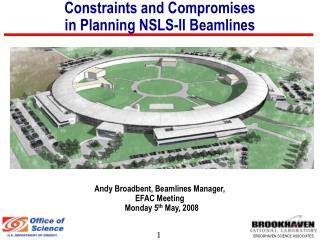
Constraints and Compromises in Planning NSLS-II Beamlines. Andy Broadbent, Beamlines Manager, EFAC Meeting Monday 5 th May, 2008. General Constraints. Safety Constraints. Building Constraints: LOBs;. General Constraints. Safety Constraints. Building Constraints: LOBs;

E N D
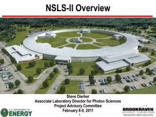
Constraints and Compromises in Planning NSLS-II Beamlines Andy Broadbent, Beamlines Manager, EFAC Meeting Monday 5th May, 2008
General Constraints • Safety Constraints. • Building Constraints: • LOBs;
General Constraints • Safety Constraints. • Building Constraints: • LOBs; • Column positions; • Floor space.
General Constraints • Safety Constraints. • Building Constraints: • LOBs; • Column positions; • Floor space. • Accelerator Constraints: • Injection straight; • RF straights; • 3 or 5 fold symmetry; • Devices on high beta straights; • Diagnostics. • Grouping of beamlines.
Safety • Emergency egress from facility. • Standard width access aisles. • 50’ maximum “dead-end” strongly recommended. • Ideally have gap between FOE and experiment stations. • This gives a exit route via a beamline “duck-under”. • Normally feasible, occasionally not possible. • Do not locate such beamlines in adjacent positions.
Choice of emergency exit routes not always possible. Care is needed in locating such beamlines.
Floor Space 10’ expansion of floor – a critical change
Dual Protein Crystallography Beamlines on a Canted Undulator Source. Layout worked out in conjunction with ACCEL who have designed a “revised GMCA-CAT” based beamline that will fit without compromise.
Beamlines passing outside the facility require a low level “bypass”, this gives the opportunity for extra floor space. …. gives about 6m of extra beamline length on experiment floor. Extra 10’ of floor length Previous vibration isolation joint position Vibration isolation
Options for DW placement with 3 or 5 fold symmetry. Symmetry Considerations Damping wigglers may only be located in high beta (even numbered) straights. The possible options are tabulated below.
Symmetry Considerations Possible damping wiggler locations: Option 1: 6,16,26 Option 2: 8,18,28 Option 3: 2,8,14,20,26
Symmetry Considerations Large Gap Dipole Chambers for Far-IR. We can take advantage of unused floor space on other side of the ratchet wall… here.
IR Cabins Horizontal extraction is desirable for the far-IR beamline. This is only possible in a few places at NSLS-II. Photos courtesy of the Australian Synchrotron
Vertical extraction scheme proposed for the mid-IR beamlines at NSLS-II
Extended Length Straights • Very desirable for IXS beamline where a very long undulator would have a significant scientific impact. • There is a feasibility study for extending straights, at the cost of reducing the length of the adjacent short straights (dipole and focusing magnets move outward). • Extended length straights would need to have three fold symmetry. • Care needs to be take with devices +/-10 straights away from IXS, plus with the adjacent six short straights. • Position would be critical as tunnel walkway would become narrower.
Devices on High Beta Straights • High field and/or short period device will cause amplitude dependent tune shift; • this is undesirable on a new machine • aim to avoid making commissioning any more difficult • carefully select devices for high beta straights to give no greater impact than DWs. • Superconducting wigglers cannot go on high beta straights. • IVU specifications need to be carefully reviewed prior to locating on a high beta straight.
Grouping of Beamlines: Scientific Villages • Many User groups expressed the desire to co-locate beamlines with a similar theme, for example; • one sample, several techniques, • laboratory requirements, • sample environments. • Efficiency of facility staffing. • Promote User interaction. • Promote sharing of a single technique between communities. • Dynamic scientific environment for facility staff.
Summary • There are lots of constraints. • Strawman layout does not currently exist. • We cannot satisfy everyone! • Some compromises are needed. • Advice or comment sought from EFAC