PCI LOCAL BUS Peripheral Component Interconnect (PCI).
660 likes | 1.45k Vues
PCI LOCAL BUS Peripheral Component Interconnect (PCI). . Local Bus Concept. More bandwidth Video Card Hard disks Faster CPUs But still slow IO bus Bus close to CPU and memory bus. Backside Bus Frontside Bus PCI Direct access to system memory for connected devices

PCI LOCAL BUS Peripheral Component Interconnect (PCI).
E N D
Presentation Transcript
PCI LOCAL BUS Peripheral Component Interconnect (PCI).
Local Bus Concept • More bandwidth • Video Card • Hard disks • Faster CPUs • But still slow IO bus • Bus close to CPU and memory bus
Backside Bus Frontside Bus PCI Direct access to system memory for connected devices Uses a bridge to connect to the frontside bus and therefore to the CPU Dual Independent Bus (DIB)
Bus Type Bus Width Bus Speed MB/sec ISA 16 bits 8 MHz 16 MBps EISA 32 bits 8 MHz 32 MBps VL-bus 32 bits 25 MHz 100 MBps VL-bus 32 bits 33 MHz 132 MBps PCI 32 bits 33 MHz 132 MBps PCI 64 bits 33 MHz 264 MBps PCI 64 bits 66 MHz 512 MBps PCI 64 bits 133 MHz 1 GBps Bus Comparisons
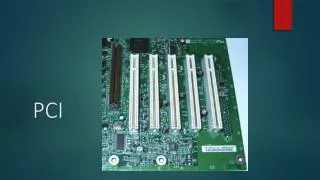
A typical PCI card Typical PCI Card PCI card – 47 pins
PCI Revision 2.1 Features • Processor independence • Low-power consumption • Burst use for all read and write transfers • Bus speed up to 66 MHz • 64-bit bus width • Low pin count (PCI Target: 47,PCI Initiator: 49 pins) • Concurrent bus operation • Bus master support • Hidden bus arbitration • Auto configuration
Intro to PCI Bus Operation Key Terms • Initiator • — Or Master • — Owns the bus and initiates the data transfer • — Every Initiator must also be a Target • Target • — Or Slave • — Target of the data transfer (read or write) • Agent • — Any initiator/target or target on the PCI bus
Intro to PCI Bus Operation PCI Bus Clock • All action synchronize to the PCI clock • Clock may be any where from 0 MHz to 33 MHz and all PCI device must be support this range • The revision 2.1 specification define speed up to 66 MHz Address phase • At the same time, initiator identifiers target device and the type of transaction • The initiator assert the FRAME# signal • Every PCI target device latch the address and decode it
Intro to PCI Bus Operation Data Phase • Number of data bytes to be transformed is determined by the number of Command/Byte Enable signals asserted by initiator • Both of initiator and target must t ready to complete data phase • IRDY# and TRDY# used Transaction Duration • By asserting FRAME# at start of address phase and remain until the final data phase
Intro to PCI Bus Operation Transaction completion and return of bus to idle state • By deasserting the FRAME# but asserting IRDY# • When the last data transfer has completed the initiator returns the PCI bus to idle state by deasserting IRDY#
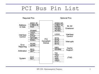
- Clock and Reset Transaction Control Initiator Signals Target Signals Configuration Signals Address and Data Signals Arbitration Signals Error Signals PCI Signals
Clock and Reset • CLK • — PCI input clock • — All signals sampled on rising edge • — 33MHz is really 33.33333MHz (30ns clk. period) • — The clock is allowed to vary from 0 to 33 MHz • – The frequency can change “on the fly” • – Because of this, no PLLs are allowed • RST# • — Asynchronous reset • — PCI device must tri-state all I/Os during reset
Transaction ControlTarget Signals • TRDY# – I/O • — “T-Ready” • — When the target asserts this signal, it tells the initiator that it is ready to send or receive data • STOP# – I/O • — Used by target to indicate that it needs to terminate the • transaction
Transaction Control Target Signals • DEVSEL# – I/O • — Device select • — Part of PCI’s distributed address decoding • – Each target is responsible for decoding the address associated with each transaction • – When a target recognizes its address, it asserts DEVSEL# to claim the corresponding transaction
Transaction Control Initiator Signals • FRAME# – I/O • — Signals the start and end of a transaction • IRDY# – I/O • — “I-Ready” • — Assertion by initiator indicates that it is ready to send receive data
Transaction Control Configuration Signals • Uses the same signals as the target, plus . . . • IDSEL – I • — “ID-Sel” • — Individual device select for configuration – one unique IDSEL line per agent • — Solves the “chicken-and-egg” problem • – Allows the system host to configure agents before these agents know the PCI addresses to which they must respond
Address and Data Signals • AD[31:0] – I/O • — 32-bit address/data bus • — PCI is little endian (lowest numeric index is LSB) • C/BE#[3:0] – I/O • — 4-bit command/byte enable bus • — Defines the PCI command during address phase • — Indicates byte enable during data phases • – Each bit corresponds to a “byte-lane” in AD[31:0] – for example,C/BE#[0] is the byte enable for AD[7:0]
Address and Data Signals • PAR – I/O • — Parity bit • — Used to verify correct transmittal of address/data and command/byte-enable • — The XOR of AD[31:0], C/BE#[3:0], and PAR should return zero (even parity) • – In other words, the number of 1’s across these 37 signals should be even
Arbitration Signals • For initiators only! • REQ# – O • — Asserted by initiator to request bus ownership • — Point-to-point connection to arbiter – each initiator has its own REQ# line • GNT# – I • — Asserted by system arbiter to grant bus ownership to the initiator • — Point-to-point connection from arbiter – each initiator has its own GNT# line
Error Signals • PERR# – I/O • — Indicates that a data parity error has occurred • — An agent that can report parity errors can have its PERR# turned off during PCI configuration • SERR# – I/O • — Indicates a serious system error has occurred • – Example: Address parity error • — May invoke NMI (non-maskable interrupt, i.e., a restart) in some systems
Basic Bus Operations Terms • Doubleword • — 32 bits, most often known as a “DWORD” • Quadword • — 64 bits, sometimes known as a “QWORD” • Burst transaction • — Any transaction consisting of more than one data phase • Idle state (no bus activity) • — Indicated by FRAME# and IRDY# deasserted
Example #1 – Basic Write • A four-DWORD burst from an initiator to a target
Write Example – Things to Note • The initiator has a phase profile of 3-1-1-1 • — First data can be transferred in three clock cycles (idle + address +data = “3”) • — The 2 nd , 3 rd , and last data are transferred one cycle each (“1-1-1”)
Write Example – Things to Note • The target profile is 5-1-1-1 • — Medium decode – DEVSEL# asserted on 2 nd clock after FRAME# • — One clock period of latency (or wait state) in the beginning of the transfer • – DEVSEL# asserted on clock 3, but TRDY# not asserted unti clock 4 • — Ideal target write is 3-1-1-1 • Total of 4 data phases, but required 8 clocks • — Only 50% efficiency
Target Address Decoding • PCI uses distributed address decoding • — A transaction begins over the PCI bus • — Each potential target on the bus decodes the transaction’s PCI address to determine whether it belongs to that target’s assigned address space • – One target may be assigned a larger address space than another, and would thus respond to more addresses • — The target that owns the PCI address then claims the transaction by asserting DEVSEL#
Target Decode • Address decoders come in different speeds • If a transaction goes unclaimed (nobody asserts DEVSEL#), “Master Abort” occurs
Example #2 – Target Read • A four-DWORD burst read from a target by an initiator
More Terms • Turnaround cycle • — “Dead” bus cycle to prevent bus contention • Wait state • — A bus cycle where it is possible to transfer data, but no data • transfer occurs • — Target deasserts TRDY# to signal it is not ready • — Initiator deasserts IRDY# to signal it is not ready • Target termination • — Target asserts STOP# to indicate that it needs to terminate the current transaction
Target Read – Things to Note • Wait states may be inserted dynamically by the initiator or target by deasserting IRDY# or TRDY# • Either agent may signal the end of a transaction • — The target signals termination by asserting STOP# • — The initiator signals completion by deasserting FRAME#
Zero and One Wait State • A one-wait-state agent inserts a wait state at the beginning of each data phase • — This is done if an agent – built in older, slower silicon – needs to pipeline critical paths internally • — Reduces bandwidth by 50%
Zero and One Wait State • The need to insert a wait state is typically an issue only when the agent is sourcing data (initiator write or target read) • — This is because such an agent would have to sample its counterpart’s xRDY# signal to see if that agent accepted data,then fan out to 36 or more clock enables (for AD[31:0] and possibly C/BE#[3:0]) to drive the next piece of data onto the PCI bus . . . all within 11 ns! • – And even that 11 ns would be eaten up by a chip’s internal clock-distribution delay
PCI Addressing and Bus Commands
PCI Address Space • A PCI target can implement up to three different types of address spaces • — Configuration space • – Stores basic information about the device • – Allows the central resource or O/S to program a device with operational settings • — I/O space • – Used mainly with PC peripherals and not much else • — Memory space • – Used for just about everything else
Types of PCI Address Space • Configuration space • — Contains basic device information, e.g., vendor or class of device • — Also permits Plug-N-Play • – Base address registers allow an agent to be mapped dynamically into memory or I/O space • – A programmable interrupt-line setting allows a software driver to program a PC card with an IRQ upon power-up (without jumpers!)
Types of PCI Address Space • Configuration space (cont’d) • — Contains 256 bytes • – The first 64 bytes (00h – 3Fh) make up the standard configuration header, predefined by the PCI spec • – The remaining 192 bytes (40h – FFh) represent user-definable configuration space • • This region may store, for example, information specific to a PC card for use by its accompanying software driver
IO Space • — This space is where basic PC peripherals (keyboard, serial port,etc.) are mapped • — The PCI spec allows an agent to request 4 bytes to 2GB of I/O space • – For x86 systems, the maximum is 256 bytes because of legacy ISA issues
Memory Space • Memory space • — This space is used by most everything else – it’s the general-purpose address space • – The PCI spec recommends that a device use memory space, even if it is a peripheral • — An agent can request between 16 bytes and 2GB of memory space • – The PCI spec recommends that an agent use at least 4kB of memory space, to reduce the width of the agent’s address decoder
PCI Commands • PCI allows the use of up to 16 different 4-bit commands • — Configuration commands • — Memory commands • — I/O commands • — Special-purpose commands • A command is presented on the C/BE# bus by the initiator during an address phase (a transaction’s first assertion of FRAME#)