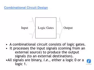
Combinational Circuit Design: Practice
This chapter focuses on deriving efficient HDL descriptions for combinational circuits, emphasizing operator and functionality sharing to optimize designs. It contrasts effective VHDL coding practices with ineffective approaches, highlighting the importance of domain knowledge in crafting concise and optimized circuits. The chapter also presents several examples demonstrating how adjustments in code can reduce circuit complexity while improving area and delay metrics. Various considerations, such as layout-related circuits and the synthesis process, are discussed to optimize the physical implementation on silicon chips.

Combinational Circuit Design: Practice
E N D
Presentation Transcript
Combinational Circuit Design: Practice Chapter 7
Outline • Derivation of efficient HDL description • Operator sharing • Functionality sharing • Layout-related circuits • General circuits Chapter 7
Derivation of efficient HDL description • Think “H”, not “L”, of HDL • Right way: • Research to find an efficient design (“domain knowledge”) • Develop VHDL code that accurately describes the design • Wrong way: • Write a C program and covert it to HDL Chapter 7
Sharing • Circuit complexity of VHDL operators varies • Arith operators • Large implementation • Limited optimization by synthesis software • “Optimization” can be achieved by “sharing” in RT level coding • Operator sharing • Functionality sharing Chapter 7
An example 0.55 um standard-cell CMOS implementation Chapter 7
2. Operator sharing • “value expressions” in priority network and multiplexing network are mutually exclusively: • Only one result is routed to output • Conditional sig assignment (if statement) sig_name <= value_expr_1 when boolean_expr_1 else value_expr_2 when boolean_expr_2 else value_expr_3 when boolean_expr_3 else . . . value_expr_n; Chapter 7
Selected sig assignment (case statement) with select_expression select sig_name <= value_expr_1 when choice_1, value_expr_2 when choice_2, value_expr_3 when choice_3, . . . value_expr_n when choice_n; Chapter 7
Example 1 • Original code: r <= a+b when boolean_exp else a+c; • Revised code: src0 <= b when boolean_exp else c; r <= a + src0; Chapter 7
Area: 2 adders, 1 mux Delay: Area: 1 adder, 1 mux Delay: Chapter 7
Example 2 • Original code: process(a,b,c,d,...) begin if boolean_exp_1 then r <= a+b; elsif boolean_exp_2 then r <= a+c; else r <= d+1; endif end process; Chapter 7
Revised code: process(a,b,c,d,...) begin if boolean_exp_1 then src0 <= a; src1 <= b; elsif boolean_exp_2 then src0 <= a; src1 <= c; else src0 <= d; src1 <= "00000001"; endif; endprocess; r <= src0 + src1; Chapter 7
Area:2 adders, 1 inc, 2 mux Area: 1 adder, 4 mux Chapter 7
Example 3 • Original code: with sel select r <= a+b when "00", a+c when "01", d+1 whenothers; • Revised code: with sel_exp select src0 <= a when "00"|"01", d whenothers; with sel_exp select src1 <= b when "00", c when "01", "00000001" whenothers; r <= src0 + src1; Chapter 7
Area: 1 adder, 2 mux Area:2 adders, 1 inc, 1 mux Chapter 7
Example 4 • Original code: process(a,b,c,d,...) begin if boolean_exp then x <= a + b; y <= (others=>'0'); else x <= (others=>'1'); y <= c + d; endif; end process; Chapter 7
Area:2 adders, 2 mux Chapter 7
Revised code: begin if boolean_exp then src0 <= a; src1 <= b; x <= sum; y <= (others=>'0'); else src0 <= c; src1 <= d; x <= (others=>'1'); y <= sum; endif; end process; sum <= src0 + src1; Chapter 7
Area: 1 adder, 4 mux • Is the sharing worthwhile? • 1 adder vs 2 mux • It depends . . . Chapter 7
Summary • Sharing is done by additional routing circuit • Merit of sharing depends on the complexity of the operator and the routing circuit • Ideally, synthesis software should do this Chapter 7
3. Functionality sharing • A large circuit involves lots of functions • Several functions may be related and have common characteristics • Several functions can share the same circuit. • Done in an “ad hoc” basis, based on the understanding and insight of the designer (i.e., “domain knowledge”) • Difficult for software it since it does not know the “meaning” of functions Chapter 7
e.g., add-sub circuit Chapter 7
Manual injection of carry-in: Append an additional bit in right (LSB): Chapter 7
e.g., sign-unsigned comparator Chapter 7
Binary wheel Chapter 7
Observation: • Unsigned: normal comparator • Signed: • Different sign bit: positive number is larger • Same sign: compare remaining 3 LSBsThis works for negative number, too!E.g., 1111 (-1), 1100 (-4), 1001(-7) 111 > 100 > 001 • The comparison of 3 LSBs can be shared Chapter 7
e.g., Full comparator Chapter 7
Read 7.3.3 and 7.3.5 Chapter 7
4. Layout-related circuits • After synthesis, placement and routing will derive the actual physical layout of a digital circuit on a silicon chip. • VHDL cannot specify the exact layout • VHDL can outline the general “shape” Chapter 7
Silicon chip is a “square” • “Two-dimensional” shape (tree or rectangular) is better than one-dimensional shape (cascading-chain) • Conditional signal assignment/if statement form a single “horizontal” cascading chain • Selected signal assignment/case statement form a large “vertical” mux • Neither is ideal Chapter 7
e.g., Reduced-xor circuit Chapter 7
Comparison of n-input reduced xor • Cascading chain : • Area: (n-1) xor gates • Delay: (n-1) • Coding: easy to modify (scale) • Tree: • Area: (n-1) xor gates • Delay: log2n • Coding: not so easy to modify • Software should able to do the conversion automatically Chapter 7
e.g., Reduced-xor-vector circuit Chapter 7
Direct implementation Chapter 7
Functionality Sharing Chapter 7
Direct tree implementation Chapter 7
“Parallel-prefix” implementation Chapter 7
Comparison of n-input reduced-xor-vector • Cascading chain • Area: (n-1) xor gates • Delay: (n-1) • Coding: easy to modify (scale) • Multiple trees • Area: O(n2) xor gates • Delay: log2n • Coding: not so easy to modify • Parallel-prefix • Area: O(nlog2n) xor gates • Delay: log2n • Coding: difficult to modify • Software is not able to convert cascading chain to parallel-prefix Chapter 7
e.g., Shifter (rotating right) • Direct implementation Chapter 7