Download
1 / 25
250 likes | 410 Vues
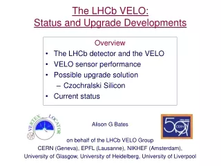
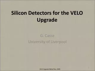
Silicon Detectors for the VELO Upgrade. G. Casse University of Liverpool. Planar Silicon Sensor issues:. Pros: Well known technology with standard processing Many commercial suppliers including those capable of delivering the orders

E N D
Silicon Detectors for the VELO Upgrade G. Casse University of Liverpool VELO Upgrade Nikhef Nov. 2009.
Planar Silicon Sensor issues: • Pros: • Well known technology with standard processing • Many commercial suppliers including those capable of delivering the orders • High yield and relatively lost cost (particularly if single-sided n-in-p) • Long experience with sensor design and optimization • Processing of thinned detectors established with commercial suppliers • Minimum ionising particle charge collection studied after doses to 2×10¹⁶neq/cm2 • Cons: • Lower signal for a given leakage current/power consumption than other technologies • Highest dose regions might require lower electronics threshold • Lower temperatures required for highest does regions than other technologies • Highest dose regions require higher voltages than other technologies • Edgeless detector designs requires a non-planar technological step • Signals at highest doses look to rely on multiplication effects which are still poorly understood Planar silicon or else? Radiation tolerance. Limit of planar silicon sensors VELO Upgrade Nikhef Nov. 2009.
Detector power dissipation and signal Sensor thickness: Black: 300µm Red: 140µm 3 VELO Upgrade Nikhef Nov. 2009.
Reverse current after various doses: expectations and measurements Expectations: bulk generated current, proportional to f, the generation volume defined as the fully depleted fraction of the sensor. VFD: 5E14 neq cm-2 ~ 500V 1E15 neq cm-2 ~ 1000V 5E15 neq cm-2 ~ 5000V 1E16 neq cm-2 ~ 10000V 2E16 neq cm-2 ~ 20000V IR=a×f×V VELO Upgrade Nikhef Nov. 2009.
Planar Silicon Sensor issues: Planar silicon or else? Radiation tolerance. Limit of planar silicon sensors Advantages of planar silicon sensors Optimising thickness. VELO Upgrade Nikhef Nov. 2009.
CCE (n-in-p) at various fluences, and comparison 140-300mm thick sensors after 1 and 2x10¹⁶neq cm-2. VELO Upgrade Nikhef Nov. 2009.
Planar Silicon Sensor issues: Planar silicon or else? Radiation tolerance. Limit of planar silicon sensors Advantages of planar silicon sensors Optimising thickness. Anything to win with other Silicon crystals? VELO Upgrade Nikhef Nov. 2009.
Material Comparison 900 V Appears once trapping dominates, all n-strip readout choices studied are the same after neutron irradiation • After ~5×10¹⁴ n cm-2, n-in-n FZ, n-in-p FZ, n-in-p MCz very similar • At higher voltage n-in-n MCz superior up to maximum fluence (1015 n cm-2) • Need higher fluence data to determine if this continues • p-in-n shows inferior performance as expected VELO Upgrade Nikhef Nov. 2009.
Planar Silicon Sensor issues: Planar silicon or else? Radiation tolerance. Limit of planar silicon sensors Advantages of planar silicon sensors Optimising thickness. Anything to win with other Silicon crystals? The radiation tolerance R&D will be focused to obtained the sufficient signal at lower bias voltages and possibly for less power dissipation. Follow the charge multiplication R&D: other parameters besides thickness? Crucial aspects: services (HV and cooling -> module design). Running scenario: optimise annealing (reduce current and improve signal). VELO Upgrade Nikhef Nov. 2009.
What geometry? Do we need a Vespa? …. maybe a faster VELO could do!!
… where the faster VELO could be our existing geometry with improvement on the read-out. Detector could be the same, but the read-out speed and early intelligence in data processing could be much improved. The obvious advantage would be the small number of channels. Would resolution be sufficient and at what point (luminosity) the occupancy will kill the efficiency?
VESPA 50cc … short strip approach, where the strips of the existing R and Phi detectors are segmented (strip number*3/4). This would require a big effort in routing, would not lead to a better resolution, would keep occupancy low. Still back to back detectors would be required, signal to noise improved due to the smaller cell size (lower input capacitance to the electronics).
VESPA 125cc … strixelapproach, where the pixel dimensions could be in the order of 50µmx400-1000µm. Large number of channels, for the required resolution probably still need R and Phi back to back detectors, difficult read-out routing (need for 3-d integration techniques). Good S/N, low occupancy.
VESPA 250cc … wedge-xelapproach, where the pixel dimensions change with radius. Very problematic routing and positioning of the electronics if the pixel density is high (the dimension of the electronics chip is decoupled from the dimensions of the sensor), but the dimensions of the wedged-shape pixels should be such that 2-d information is delivered by one detector. Good S/N, low occupancy.
…or, if you need more power ….. Full square hybrid pixel design (BTev, with flip-chip electronics bump bonded to the sensors (or new soldering technologies), the size you like (probably in the future will be possible to go below 25µm diameter contacts). Hi resolution achievable, low occupancy and S/N. huge number of channels.
Planar Silicon Sensors: Geometry Pixel or microstrip? Pixels: possible one detector plane/station. High density (what will be the minimum pixel size in a few years? Micro-connectivity to ASICs?), trading between channel number/point resolution. One plane -> square pixels: advantages in changing pixel dimensions with radius? Tessellation: size of a module limited (at least in one dimension) by the reticule size of the electronics. Need for 2-4 detector tiles for covering the area. Issue of dead area at sensor ends (GR+dead silicon). Slim edge planar sensors to be developed. Nonetheless, evolution in the electronics (3-D, interconnectivity and TSV) could help significantly and the need for slim edges could be confine to the sensor outer edge (with electronics ASIC tiling a single silicon pixel sensor). Microstrips: two detector planes per station. Possible high resolution with reduced number of channels (with strip pitch <50mm). Individual channel size (strip length) dictated by occupancy. Complicated routing is anticipated. One sensor to cover the area, no need for tiling. VELO Upgrade Nikhef Nov. 2009.
Planar Silicon Sensors R&D Alternative Silicon crystal material (to high-res FZ n or p-type)(nMCz, duration 6 months, not essential). Double sided processing, GR and slim edge (duration 18 months, important for both pixels and microstrips). Thickness optimisation: several issues, signal, cost and mechanics (24 months, important, possibly in conjunctions with junction geometry studies). Charge multiplication: follow RD50 developments/do own research. Required bias and cooling: power predictions (reverse current) not easily extrapolated. Direct tests required, need to keep safe margin. Pixels: possible one detector plane/station. High density, trading between channel number/point resolution. One plane -> square pixels: advantages in changing pixel dimensions with radius? This research implies cutting edge activities in conjunction with ASICS/post processing manufacturers, interconnectivity issues. Microstrips: two detector planes per station. Possible high resolution with reduced number of channels (with strip pitch <50mm). Individual channel size (strip length) dictated by occupancy. Complicated routing is anticipated. VELO Upgrade Nikhef Nov. 2009.
A few spare slides VELO Upgrade Nikhef Nov. 2009.
“Fine step” Annealing of the colleted charge, HPK FZ n-in-p, 1E15 n cm-2 Neutron irradiations in Ljubljana, neutrons are dominating the radiation damage > 25 cm radius. VELO Upgrade Nikhef Nov. 2009.
“Fine step” CCE Annealing 1.5E16 n cm-2 Irradiated with 26MeV protons (Karlsruhe). Noise is the sum in quadrature of shot noise and parallel noise (taken from the Beetle chip specs, and estimated as 650ENC) VELO Upgrade Nikhef Nov. 2009.
nnealing of the reverse current, Micron n-in-p, after 1.5E16 neq cm-2 (26 MeV p irradiation) VELO Upgrade Nikhef Nov. 2009.
Qtc Q0exp(-tc/ttr), 1/ttr = bF. Expected signal from charge trapping vsat,e x ttr = lav G. Kramberger et al., NIMA 476(2002), 645-651. Effect of trapping on the Charge Collection Distance be = 4.2E-16 cm-2/ns bh = 6.1E-16 cm-2/ns After heavy irradiation it seems that the VFD is lower than expected from extrapolation from lower doses. This could yield a larger signal. But, is depletion the limiting factor after heavy irradiation? In fact, the charge trapping at radiation induced defect centres has a larger effect on the signal. The collection distance at saturation velocity: lav after 1x10¹⁵ neq cm-2: 240µm (expected charge ~19ke). lav after 5x10¹⁵ neq cm-2: 50µm (expected charge <4ke). lav after 1x10¹⁶ neq cm-2: 25µm (expected charge <1.3ke). lav after 2x10¹⁶ neq cm-2: 12µm (expected charge <1ke). VELO Upgrade Nikhef Nov. 2009.
Moreover there is clear indication of a charge multiplication mechanism after irradiation. A rather marginal improvement of the CCE is found by going from -25oC to -50oC. But there is substantial evidence of charge multiplication. 140 and 300 mm n-in-p Micron sensors after 5x10¹⁵ neq 26MeV p VELO Upgrade Nikhef Nov. 2009.
Possible solutions to an optimised cell layout can come from recent developments G. Casse, VELO Spares and Upgrade, Ness Gardens, Oct. 2007
Possible solutions? • Sensor wafer 2) Add dielectric and open vias 3)Add metal layers and pattern 5) Flip-chip ASICs 4) Dice sensor 6)Wirebond to hybrid Part of MCM-D? G. Casse, VELO Spares and Upgrade, Ness Gardens, Oct. 2007