Express Virtual Channels for Efficient Interconnection Networks
110 likes | 203 Vues
Explore how Express Virtual Channels optimize routing, allocation, and traversal stages in Interconnection Fabrics. Learn about bypass and aggressive router pipelines for improved data transmission. Discuss the potential of Dynamic EVCs and VC Allocation strategies for enhanced network performance. Delve into the concept of an Ideal Network and its benefits.

Express Virtual Channels for Efficient Interconnection Networks
E N D
Presentation Transcript
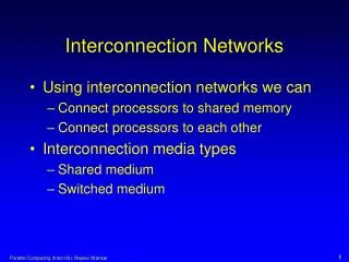
Lecture 23: Interconnection Networks • Paper: • Express Virtual Channels: Towards the Ideal • Interconnection Fabric, ISCA’07, Princeton
Router Pipeline • Four typical stages: • RC routing computation: compute the output channel • VA virtual-channel allocation: allocate VC for the head flit • SA switch allocation: compete for output physical channel • ST switch traversal: transfer data on output physical channel Cycle 1 2 3 4 5 6 7 Head flit Body flit 1 Body flit 2 Tail flit RC VA SA ST -- -- SA ST -- -- SA ST -- -- SA ST
Express Physical Channels • Express channels connect non-adjacent nodes – flits traveling a long distance • can use express channels for most of the way and navigate on local channels • near the source/destination (like taking the freeway) • Helps reduce the number of hops • The router in each express node is much bigger now
Express Virtual Channels • To a large extent, maintain the same physical structure as a • conventional network (changes to be explained shortly) • Some virtual channels are treated differently: they go through a • different router pipeline and can effectively avoid most router • overheads
Router Pipelines • If Normal VC (NVC): • at every router, must compete for the next VC and for the switch • will get buffered in case there is a conflict for VA/SA • If EVC (at intermediate bypass router): • need not compete for VC (an EVC is a VC reserved across multiple routers) • similarly, the EVC is also guaranteed the switch (only 1 EVC can compete for an output physical channel) • since VA/SA are guaranteed to succeed, no need for buffering • simple router pipeline: incoming flit directly moves to ST stage • If EVC (at EVC source/sink router): • must compete for VC/SA as in a conventional pipeline • before moving on, must confirm free buffer at next EVC router
Bypass Router Pipelines • Non aggressive pipeline in a bypass node: an express flit simply • goes through the crossbar and then on the link; the prior SA stage • must know that an express flit is arriving so that the switch control • signals can be appropriately set up; this requires the flit to be • preceded by a single-bit control signal (similar to cct-switching, but • much cheaper) • Aggressive pipeline: the express flit avoids the switch and heads • straight to the output channel (dedicated hardware)… will still need • a mechanism to control ST for other flits
Dynamic EVCs • Any node can be an EVC source/sink • The EVC can have length 2 to lmax
VC Allocation • All the VCs at a router are now partitioned into lmax bins • More buffers for short-hop EVCs • Flow control credits have to propagate lmax nodes upstream • Can also dynamically allocate buffers to EVCs (although • one buffer must be reserved per EVC to avoid deadlock) • EVCs can potentially starve NVCs at bypass nodes: if a • bypass node is starved for n cycles, it sends a token • upstream to prevent EVC transmission for the next p cycles
Ideal Network • Fully-connected: every node has a dedicated link to every other node • Bisection bandwidth: • For a 7x7 network, Ledge will be 69mm and chip area will be 4760mm2 • (for a single metal layer) • An ideal network will provide the least latency, least power, and • highest throughput, but will have an inordinate overhead, as • specified above
Results • Roughly 40% of all nodes are bypassed
Title • Bullet