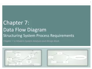
Chapter 7 Structuring System Process Requirements
Chapter 7 Structuring System Process Requirements. Objectives:. Understand logical process modeling via data flow diagrams (DFDs). Draw DFDs of well structured process models. Decompose DFDs into lower-level diagrams. Balance high-level and low-level DFDs.

Chapter 7 Structuring System Process Requirements
E N D
Presentation Transcript
Objectives: • Understand logical process modeling via data flow diagrams (DFDs). • Draw DFDs of well structured process models. • Decompose DFDs into lower-level diagrams. • Balance high-level and low-level DFDs. • Explain differences between current physical, current logical, new physical, and new logical DFDs. • Use DFDs for analyzing information systems. • Explain use cases and use case diagrams.
Process Modeling • Graphically represent the processes that capture, manipulate, store, and distribute data between a system and its environment and among system components: • System can be logical, physical, automated or manual • Data Flow Diagram (DFD) is the traditional process modeling technique of structured analysis and design • Utilize information gathered during requirements determination
Process Modeling • A process model is only one of three views of an information system • DFDs show the movement of data between external entities and the processes and data stores within a system • The processing logic and timing of events and the structure of data in the system must also be modeled.
Deliverables and Outcomes • Context data flow diagram (DFD) • Scope of system, what’s inside/outside the system • DFDs of current physical and logical system • Physical shows which people and technologies are used to move and transform data • Logical shows what data processing functions are performed by the current system • Enables analysts to understand current system • DFDs of new logical system • Technology independent • Show data flows, structure, and functional requirements of new system
Data Flow Diagram (DFD) • A picture of the movement of data between external entities and the processes and data stores within a system • Difference from system flowcharts: • DFDs depict logical data flow independent of technology • Flowcharts depict details of physical systems • May result in a premature physical system design • Automated vs. manual systems
Data Flow • Data in motion, moving from one place in a system to another • It is data that moves together: • Data on a customer order form or payroll check • Results of a database query • Contents of a printed report or a data entry form • Individual pieces of data that are generated at the same time and that flow together to common destinations
DFD Symbols • Process: work or actions performed on data (inside the system) so that they are transformed, stored or distributed • Data store: data at rest (inside the system) • File folder, computer-based file • Source/sink: external entity that is origin or destination of data (outside the system) • An organizational unit, person, information system • Data flow: arrows depicting movement of data, labeled with a meaningful name for the data in motion (customer order)
Data Flow Diagramming Rules Two overall guidelines: • The inputs to a process are different from the outputs of that process • In some cases, the same input goes in and out of the process, but other new data flows are produced as a result of manipulating the input • Objects on a DFD have unique names • Every process has a unique name • Data store and sources/sinks may repeat • When two arrows have the same data flow name, you must be certain that these flows are exactly the same
ProcessRules No process can have only outputs or only inputs…processes must have both outputs and inputs.
Data Store Rules All flows to or from a data store must move through a process.
Source/Sink Rules No data moves directly between external entities without going through a process. Interactions between external entities without intervening processes are outside the system and therefore not represented in the DFD.
Data Flow Rules Bidirectional flow between process and data store is represented by two separate arrows (read before update) Forked data flow must refer to exact same data item (not different data items) from a common location to multiple destinations.
Data Flow Rules Joined data flow must refer to exact same data item (not different data items) from multiple sources to a common location. Data flow cannot go directly from a process to itself, must go through intervening processes.
Data Flow Rules • Data flow from a process to a data store means update (insert, delete or change). • Data flow from a data store to a process means retrieve or use. • Data flow labels should be noun phrases.
Functional Decomposition • High-level processes described in terms of lower-level sub-processes • DFD charts created for each level of detail
DFD Levels • Context DFD • Overview of the organizational system • Level-0 DFD • Analyst must determine which processes are represented by the single process in the process diagram • Representation of system’s major processes at high level of abstraction • Level-1 DFD • Results from decomposition of Level 0 diagram • Level-n DFD • Results from decomposition of Level n-1 diagram
Data Flow Repository Entry • The label name for the data flow as entered on the DFD • Short description • List of data elements contained in the data flow • Notes explaining context and nature of this repository object • A list of locations on which the data flow appears and the names of the sources and destinations on each of these DFDs for the data flow
Context Diagram Context diagram shows the system boundaries, external entities that interact with the system, and major information flows between entities and the system. NOTE: only one process symbol, and no data stores shown. Process 0 is the entire system.
Level 0 DFD • Analyst must determine which processes are represented by the single process in the context diagram • Four separate processes are identified for Hoosier Burger • These main processes represent the major functions of the system • Often correspond to the activities on the main system menu
Level-0 DFD shows the system’s major processes, data flows, and data stores at a high level of abstraction. In process 1.0, order is processed, four streams of data result.
Level-1 DFD shows the sub-processes of one of the processes in the Level-0 DFD. This is a Level-1 DFD for Process 4.0. Note: source/sinks not shown
Level-n DFD is the result of n nested decompositions from a process on a level-0 diagram Level 2 diagram showing the decomposition of Process 4.3 from the level-1 diagram for Process 4.0
DFD Balancing • The conservation of inputs and outputs to a data flow process when that process is decomposed to a lower level • Balanced means: • Number of inputs to lower level DFD equals number of inputs to associated process of higher-level DFD • Number of outputs to lower level DFD equals number of outputs to associated process of higher-level DFD
Four Different Types of DFD • Current Physical • Process labels identify technology (people or systems) used to process the data. • Data flows and data stores identify actual name of the physical media. • Current Logical • Physical aspects of system are removed as much as possible. • Current system is reduced to data and processes that transform them.
Four Different Types of DFD • New Logical • Includes additional functions • Obsolete functions are removed • Inefficient data flows are reorganized • New Physical • Represents the physical implementation of the new system
Is Creating Four DFDs Really Necessary? • Begin as quickly as possible with a new logical DFD • In the past, analysts tended to devote a great amount of time creating DFDs for the current systems, most of which was thrown away in transition to the current logical DFDs • Create a set of DFDs for the current physical system, but only detailed enough to provide a good overview of the current system
Using DFDs as Analysis Tools • Gap Analysis • The process of discovering discrepancies between two or more sets of DFDs or discrepancies within a single DFD: • Is data being captured redundantly? • Data captured but not used by the system • Data updated identically in more than one location • Comparing current and new logical DFDs – what can be reused • Comparing alternative DFDs – evaluate competing opinions • Inefficiencies in a system can often be identified through DFDs.
Use Cases • Shows behavior or functional requirements of a system • Another way to model a system which describes the behavior of a system under various conditions as the system responds to requests from users • Primarily used with object-oriented analysis and design but flexible enough for other approaches
<<include>> <<extend>> UML Use Case Diagram Symbols Use Case Actor Boundary Connection Include relationship Extend relationship
What is an Actor? • Actor is an external entity that interacts with the system and exchanges info with the system. • Most actors represent user roles, but actors can also be external systems. • An actor is a role, not a specific user; one user may play many roles, and an actor may represent many users. • Use case represents a sequence of related actions initiated by an actor to accomplish a specific goal; it is a specific way of using the system
What is a Boundary? • A boundary is the dividing line between the system and its environment. • Use cases are within the boundary. • Actors are outside of the boundary.
What is a Connection? • A connection is an association between an actor and a use case. • Depicts a usage relationship • Connection does not indicate data flow
What is an <<extend>> Relationship? • A connection between two use cases • Extends a use case by adding new behavior or actions • Specialized use case extends the general use case
What is an <<include>> Relationship? • A connection between two use cases • Indicates a use case that is used (invoked) by another use case • Links to general purpose functions, used by many other use cases
Written Use Cases • Document containing detailed specifications for a use case • Contents can be written as simple text or in a specified format