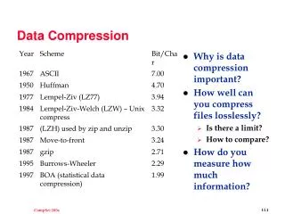
Lecture 10: data compression
Lecture 10: data compression. Email: evi@fsktm.upm.edu.my. EVI INDRIASARI MANSOR. Tel ext: 1741. Outline. Basics of Data Compression Text & N u meric Compression Image Compression Audio Compression Video Compression Data Security Through Encryption. Basics of Data Compression.

Lecture 10: data compression
E N D
Presentation Transcript
Lecture 10:data compression Email: evi@fsktm.upm.edu.my EVI INDRIASARI MANSOR Tel ext: 1741
Outline • Basics of Data Compression • Text & Numeric Compression • Image Compression • Audio Compression • Video Compression • Data Security Through Encryption
Basics of Data Compression • Digital compression concepts • Compression techniques are used to replace a file with another that is smaller • Compressed data requires less storage and can be transmitted at a faster rate • Decompression techniques expands the compressed file to recover the original data – either exactly or in facsimile • A pair of compression / decompression techniques that work together is called a codec for short
Motivations • Basically, data compression deals with reducing the number of bits used to represent a certain amount of data by removing redundancy • Motivations: • Compressed data is smaller and requires less (physical) storage [hence allowing more things to be stored at a lower cost] • Smaller amounts of data can be processed faster • Smaller data can be transmitted faster • Computing resources requirements (such as memory) can be minimized
Types of data compression • Logical compression • Generally for databases • E.g. Instead of allocating a large field size for ‘faculty name’ in a university database… a reference number can be used instead (something like the Color Lookup table scheme) • Physical compression • Deals with removal of redundancy in data • This chapter will deal only with this type of compression
Uncompressed data Compression / coder Compressed data 10010110010 CODEC 10101011100 Decompression / decoder Basics of Data Compression (cont) • Compress Decompress –CoDec • Main function ofCODEC: toreduce the redundancy in data (CODEC can also be CODE DECODE ) • How ??? – by replacing definable patterns with shorter sequences of symbols
LOSSY compression • What is it? (again…) • The compressed (and then decompressed) data is not the exact match of the source • Enable better compression performance BUT… only suitable when data loss during compression has no significant effect • E.g. When compressing an image into JPEG or TIFF. Some information loss is imperceptible by the human visual system…
LOSSLESS compression • What is it? (again…) • Source data can be reconstructed (decompressed) exactly from the compressed data • Required for example, when data being sent needs to be prices and the slightest loss of data would be detrimental • E.g. Processing telemetry data from satellite… or when compressing text files
Concept of Models and Coding • A simple ‘formula’ to remember: • DATA COMPRESSION = MODELING + CODING • This scheme of modeling and coding is used to transform an input stream of symbols into output codes! • A MODELis a collection of data and rules • Fixed model predefined rules are used form compression • Adaptive model Adjustments can be made to suit the pattern of the data at run-time. Normally capable of better compression performance… • A CODER implements the algorithm that transforms the input data into output data (based on rules/infromation provided by the MODEL)
Lossless Data Compression and Applications • Here… we’ll have a look at some specific algorithms • Substitution & Dictionary Methods • Null Suppression • Run-Length Encoding • Statistical Method • Huffman Coding
Substitution & Dictionary Methods • NULL SUPPRESSION • Scans a stream of data for sequences of the NULL character • These nulls are replaced with a special pair of characters consisting of: • Indicator character (Ic); and • A Count Example: XYZØØØØØMCKKW (where the Ø are nulls) The encoded output will be: XYZIc5MCKKW (Savings from 15-bytes to 10-bytes)
Substitution & Dictionary Methods • LIMITATIONS • Needs to have 3 or more consecutive nulls… or else expansion might be achieved instead of compression • An appropriate Ic must be defined, one which does not occur in the data stream
Substitution & Dictionary Methods • Run Length Encoding (RLE) • A generalized null suppression technique • Identifies repeated characters in the data stream • Format: • Ic – repeating character – count • Example: A BBCCDDDDDDDDDEEFGGGGG will be encoded into… ABBCCIcD9EEFIcG5 • Savings from 22-bytes to 14-bytes
Other variants of the RLE Run-Length Encoding (RLE) • Some data contain a sequence of identical (sama) bytes • The RLE technique replaces these runs of data by using a marker or a counter that indicates the number of occurrences • For instance: • Uncompressed data AAAAOOOOOOOOBBBBCCCDCC • Compressed data A#4 O#8 B#4 C CC D C C • The # acts as the marker, followed by a number indicating • the number of occurrence • This example shows that each run of code is compressed to 3-bytes (i.e. A and # and 4 = 3-bytes) • [Steinmetz and Nahrstedt, 2002] • RLE can also be coded using 2-bytes (http://www.eee.bham.ac.uk/WoolleySI/All7/run_1.htm) • The first byte indicates the number of occurrence, where the second indicates the data • For instance: • Uncompressed data AAAAOOOOOOOOBBBBCCCDCC • Compressed data 4A 8O 4B C CC D C C
Other variants of the RLE Run-Length Encoding (RLE) – (2) • As a result of this, RLE manages to compress the data down a bit. • The original data = 22-bytes (AAAAOOOOOOOOBBBBCCCDCC) • RLE compresses it down to 12-bytes (4A 8O 4B C C C D C C) • Compresses more efficiently if the run of strings is long • e.g.AAAAAAAAAAAAAAAAAAAA becomes 20A • Instead of 20-bytes… the storage is brought down to just 2-bytes (1-bytes for ’20’ and 1-byte for ‘A’) • Measuring Compression Ratio • Basically, RLE compression ratio can be measure by the formula: • (original size / compressed size) : 1 • For the above example… compression ratio is 22/12 : 1, which is almost 2:1
Other variants of the RLE Run-Length Encoding (RLE) – For repetitive data sources • Consider this: 1, 3, 4, 1, 3, 4, 1, 3, 4, 1, 3, 4 • RLE 4(1,3,4) – translates to 4 occurrences of 1,3 and 4 Run-Length Encoding (RLE) – Compressed by Differencing • Consider this: 1,2,4,5,7,9,10 • RLE can also take the differences between adjacent (bersebelahan) strings and encodes them • In this case… for example… 1 and 2 = 1; 2 and 4 = 2; 4 and 5 = 1… and so on • The respective compressed differences would be 1,2,1,2, 2,1 • Further compression 3(1,2)
Data Compression RLE when you know which variant you are using, and on what kinds of data!!! • Must be sure that there is significant long runs of repeating data, so that compression is achieved instead of EXPANSION!!! • For instance: ROTI CENAI YUGOSLAV - 17-bytes • RLE 2(A), 1(C), 1(E), 1(G), 2(I), 1(L), 1(N), 2(O), 1(R), 1(S), 1(T), 1(U), 1(V), 1(Y) – 28-bytes
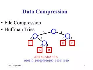
Statistical Methods • Huffman Codes • Form ofstatisticalencoding that exploits the overall distribution or frequency of symbols in a source • Produces an optimal coding for a passage-based source on assigning the fewest number of bits to encode each symbol given the probability of its occurrence • e.g. • if a passage-based content has a lot of character“e”then it would make sense to replace it with the smallest sequence of bits possible. Other characters can use its normal representation • refer the HUFFMAN tree
Data Compression Huffman Coding • This technique is based on the probabilistic distribution of symbols or characters • Characters with the most number of occurrences are assigned the shortest length of code • The code length increases as the frequency of occurrence decreases • Huffman codes are determined by successively constructing a binary tree • The leaves of the tree represent the characters to be coded • Characters are arranged in descending order of probability • The tree is further built further by repeatedly adding two lowest probabilities and resorting • This process goes on until the sum of probabilities of the last two symbols is 1 • Once this process is complete, a Huffman binary tree can be generated • The resultant code words are then formed by tracing the tree path from the root node to the end-nodes code words after assigning 0s and 1s to the branches (This assignment is arbitrary… not according to any order. So different Huffman code yield different results) • If we do not obtain a probability of 1 in the last two symbols, most likely there is a mistake in the process. This probability of 1 which forms the last symbol is the root of the binary tree
Data Compression Huffman Coding – (2) • An illustration is as follows • Let’s say you have this particular probabilistic distribution: • A = 0.10; B = 0.35; C = 0.16; D = 0.2; E = 0.19 • The characters are listed in order of decreasing probability • B = 0.35; D = 0.2; E = 0.19; C = 0.16; A = 0.10 • TWO chars. with the LOWEST probs. are combined • A = 0.10 and C = 0.16 AC = 0.26 • Re-Sort… and the new list is: • B = 0.35; AC = 0.26; D = 0.2; E = 0.19 • Then repeat what was done in step 2 (take the two lowest probs. and combine them). • D = 0.2 and E = 0.19 DE = 0.39 • Re-Sort the list again and we get: • DE = 0.39; B = 0.35; AC = 0.26
Data Compression Huffman Coding – (3) • 6. Again… get the lowest two probs. and repeat the process • B = 0.35 and AC = 0.26 BAC = 0.61 • Re-Sort… and you get the new list: • BAC = 0.61; DE = 0.39 • Finally, BAC and DE are combined… and you get BACDE = 1.0 • From all the combinations of probabilistic values that you’ve done… a binary tree is constructed. • Each edge from node to sub-node is assigned either a 1 or 0
Data Compression Huffman Coding – (4) P(BACDE) = 1.0 Huffman Code for each Character 0 1 P(BAC) = 0.61 P(DE) = 0.39 0 1 0 1 P(B) = 0.35 P(AC) = 0.26 P(D) = 0.2 P(E) = 0.19 0 1 P(C) = 0.16 P(A) = 0.10 Resultant Binary Tree
Text and Numeric Compression (cont) • Huffman Code Encoding “this is an example of a huffman tree”
Text and Numeric Compression (cont) • 3) LZW compression (Lempel-Ziv Welch) • Based on recognizing commonstring patterns • Basic strategy: replace strings in a file with bit codes rather than replacing individual characters with bit codes • Greater compressionrate than both previous methods
Lossy Data Compression and Applications • Here, we will be looking at • JPEG (Image) • MotionJPEG (Video) • MPEG (Video) • MP3 (Audio)
Joint Photographic Experts Group • JPEG for short • Extensions:.jpg, .jpeg, .jpe, .jif, .jfif, .jfi • A lossy algorithm where the reconstructed image has less information than the original • However, you won’t miss the ‘missing’ information that much since: • The human visual system does pays less attention to colour information as opposed to brightness information • The human visual system mostly does not notice the details in parts of an images that are "busy“ or “high-frequency” • Therefore, JPEG compression is suitable for images with smooth variations of tone and color (i.e. such images will compress well!)
Joint Photographic Experts Group • High frequency vs. Low frequency HIGH LOW
Joint Photographic Experts Group • How the JPEG algorithm works • An image is divided into 8X8 pixel blocks • The Discrete Cosine Transform (DCT) of each block is calculated. This converts the image from the spatial domain to the frequency domain – resulting in DCT coefficients • A quantization process rounds off the coefficients (according to some quantization matrix which determines the quality of the resulting image) – it’s in this step also that you can produce LOSSLESS Jpeg • A lossless compression technique is used to encode the coefficients of the 8X8 blocks (e.g. RLE) • For decompression… the process is reversed
Joint Photographic Experts Group 1. The 8 X 8 blocks Original values are from [0,255]. The resulting Image matrix g is after shifting (subtracting 128 from each of the elements)
Joint Photographic Experts Group 2. DCT is performed on the 8X8 block (sub-image) • The scary formula looks like this: resulting in 64-coefficients:
Joint Photographic Experts Group 2. DCT (continued) • Notice that the upper-left corner (i.e. the DC coefficient) is quite big in magnitude. These are the lower-frequency components (the ones that we are more sensitive to) • The lower-right are for the higher frequency parts (ones that we are not that sensitive to)
Joint Photographic Experts Group 3. Quantization • Compression is done here… • A bunch of numbers falling within a certain range will be assigned a specific value • Therefore, the quantization table/matrix defines just this… an 8X8 matrix of step sizes (or quantums) – (NOTE: if ALL the values in the quantization table are 1, this is when JPEG becomes LOSSLESS) • This process takes advantage of the human visual system’s ability to seeing small differences in brightness over a relatively large area… which means that we are good at making sense of low frequency images • But we are bad at differentiating exact brightness variations over small areas…
Joint Photographic Experts Group 3. Quantization (continued) • Therefore, the amount of information in the high frequency components can be reduced (or even removed) • Done by dividing each component in the frequency domain (i.e. matrix G produced by DCT) by a constant for that component, and then rounding to the nearest integer
Joint Photographic Experts Group 3. Quantization (continued) • An example quantization table/matrix as specified in the original JPEG standard:
Joint Photographic Experts Group 3. Quantization (continued) • The formula: • G is the unquantized DCT coefficients; Q the quantization matrix in the previous slide; and the result B the quantized DCT matrix • In short, each element is G is divided (and rounded up) by each corresponding component in Q (hence the indexes j and k)
Joint Photographic Experts Group 3. Quantization (continued) • The quantized DCT matrix B is as follows: • Notice that the higher frequency components (which we are not sensitive to) are rounded to ZERO, and the rest become small +/- integers • These require lesser space to store…
Joint Photographic Experts Group 3. Zig-zagging and Lossless Compression • The matrix B is then arranged and coded in a zig-zag manner… i.e. Bi(0,0), Bi(0,1), Bi(1,0), Bi(2,0), Bi(1,1), Bi(0,2), Bi(0,3), Bi(1,2) and so on -26 -3 0 -3 -2 6 2 -4 1 -3 1 1 5 1 2 -1 1 -1 2 0 0 0 0 0 -1 -1 0 0 0 0 0 0 0 0 0 0 0 0 0 0 0 0 0 0 0 0 0 0 0 0 0 0 0 0 0 0 0 0 All of these values are stored in a vector (i.e. a one dimensional array) and then coded using DCPM, Huffman and Run-length encoding
The JPEG compression/decompression process http://en.wikipedia.org/wiki/File:JPEG_process.svg
Joint Photographic Experts Group So how can JPEG become lossless again??? If you refer to the 1st Slide of the Quantization step (step-3), then it has something to do with the quantization matrix having all values of 1!!! * So please do the maths Owh, and I reckon you don’t need to do the rounding as well…
Audio Compression • The choice of sampling rates (frequency and amplitude) are very important to handle the size of an audio size • Higher sampling rates mean higher fidelity, and cost more in storage space and transmission time • Widely used method is ADPCM (Adaptive Differential Pulse Code Modulation)
Audio Compression (cont) • Adaptive Differential Pulse Code Modulation (ADPCM) • Pulse code modulation (PCM) is a basic method for quantizing audio information • Differential PCM compresses the number of bits needed to represent the data by storing the first PCM sample in its entirety and all succeeding samples as differences from the previous one • Adaptive DPCM (encoder) - takes the scheme anddividesthe values of DPCM samples by an appropriatecoefficientto produce a smaller value to store
Audio Compression (cont) • Adaptive Differential Pulse Code Modulation (ADPCM) • In playback, the decodermultipliesthe compressed data by thatcoefficientto reproduce the proper differential value • Works very well withspeech, but is less effective for music
Audio Compression (cont) • Perceptual Noise Shaping • approach used byMP3 audio format • MP3format helps reduce the number of bytes in a song without hurting the quality of the song's sound. • goal of theMP3 format • compress a CD-quality song by a factor of 10 to 14 without noticeably affecting the CD-quality sound • With MP3, a 32-megabyte (MB) song on a CD compresses down to about 3MB !!!. • MP3format uses characteristics of the human ear to design the compression algorithm
Audio Compression (cont) • Perceptual Noise Shaping (cont)
Lecture 11:data compression (2) Email: evi@fsktm.upm.edu.my EVI INDRIASARI MANSOR Tel ext: 1741
Outline • Basics of Data Compression • Text & Numeric Compression • Image Compression • Audio Compression • Video Compression • Data Security Through Encryption
Learning Outcomes • Differentiate between the lossless and the lossy data compression process
Video Compression • Transmitting standard full screen color imagery as video at 30 fps requires a data rate nearly 28MB per second • video compression is absolutely essential !!! • One idea is to reduce the amount of data rate (from 30 fps to 15 fps), but it will sacrifice a lot of video motions