Download
1 / 44
440 likes | 585 Vues
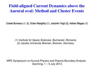
Field-aligned Current Dynamics above the Auroral oval: Method and Cluster Events. Costel Bunescu (1, 2), Octav Marghitu (1), Joachim Vogt (2), Adrian Blagau (1). (1) Institute for Space Sciences, Bucharest, Romania (2) Jacobs University Bremen, Bremen, Germany.

E N D
Field-aligned Current Dynamics above the Auroral oval: Method and Cluster Events Costel Bunescu (1, 2), OctavMarghitu (1), Joachim Vogt (2), Adrian Blagau (1) (1) Institute for Space Sciences, Bucharest, Romania (2) Jacobs University Bremen, Bremen, Germany MPE Symposium on Auroral Physics and Plasma Boundary Analysis Garching, 1 – 5 July 2013
Motivation • Can we use better the 12 years database of Cluster perigee passes in order to study FAC dynamics? • In particular, make use of the multi-point capabilities of Cluster, used e. g. to check the AAR potential structure, though not so much to investigate FAC dynamics • Proper evaluation of the FAC dynamics may result in better estimates of key parameters, like Poynting flux, current density, potential drop, field-aligned conductance / current-voltage relationship. • FAC dynamics above the AAR is directly related to the generator region in the plasma sheet. • Techniques developed for analyzing FAC structures with Cluster may help multi-point investigations with different data sets, like those of the upcoming Swarm mission.
Outline • Continuous and multi-scale evaluation of key quantites: • Time lag (2 satellites) • Orientation (MVA, 1 satellite) • Speed (requires time lag, orientation AND planar structures) • Event study – 1D arc • Satellite configuration • Spacecraft and ground data • Time lag, orientation and velocity • Event study – 2D structure • Satellite configuration • Spacecraft and ground data • Spectral analysis • Time lag, orientation and velocity derived from Cluster data • Doppler analysis of Cluster and ground data • Examination of Cluster 3 / FAST conjunction • Summary and prospects
A. Method: Intro t=t1-t4; l=r1-r4 • For ideal, planar FAC sheets, the time-lag (2 satellites) and orientation (MVA, 1 satellite) are enough to determine velocity. • For locally planar FAC structures one can still derive the normal velocity. • Locally planar => local radius of curvature (significantly) larger than FAC structure scale. • In order to fully characterize the motion of a 2D FAC structure one needs additional information, e.g. by Doppler analysis of spacecraft and ground data, or by analysis of conjugate satellite data.
A typical Cluster crossing above the auroral oval take 0.5–1 h. During this time FACs are, in general, not stationary. • At the same time, magnetic field perturbation, DB, includes contributions from a wide range of scales, from very small to very large. • Also, a specific scale range, like meso-scale (a few 100 km), often includes a set of contributions, as revealed e. g. by the spectral peaks of DB. • Challenge: Develop a continuous and multi-scale analysis method, to be used for deriving the time lag, orientation, and velocity of FAC structures. • Inspiration in Soucek et al. (Ann. Geophys., 2004), who developed a two-satellite technique and applied it to magnetopause crossings (~1 min intervals). A. Method: Intro
Maximum correlation at each tk Time lag t Time Time lag t Time lag t Time lag t Scale Time Time Time A. Method: Time Lag • Non-stationary, one scale: • Compute cross-correlation over a sliding window of given width / scale, C (t, t), and take t0 that maximizes C. • Non-stationary, multi-scale: • Compute cross-correlation over a set of sliding windows, covering a range of widths / scales, C (t, t, w), and at each time show the histogram over scales, N (t, t). • The peak value of the histogram, t0, provides a proxy for the time lag. • The standard deviation provides a proxy for the time lag error.
A. Method: Time Lag • Synthetic signals S1, S2: • S1: 1.5 mHz + 9/10 3.5 mHz • S2: 1.5 mHz + 2/5 3.5 mHz • Time shift in phase of 40 s • Time lag of 40 s correctly reproduced.
A. Method: Time Lag • Synthetic signals S1, S2: • S1: 1.5 mHz + ½ 3.5 mHz • S2: 1.5 mHz + ½ 3.2 mHz • Time shift in phase of 40 s • Narrow peak of the histogram => ‘structure’ behaviour. • The time varying time lag changes with a period of ~3300 s, consistent with the beats of S1 and S2, Dn=0.3 mHz.
40 20 0 -20 -40 -40 -20 0 20 40 • DB for a current filament, R=10. • White = satellite crossing at 0.5 R. • MVA over scale from 0.5R to R. A. Method: Orientation • Orientation can be investigated similar to the time lag, by computing the minimum variance direction, q, over a set of sliding windows, q (t, w), and then showing at each time the histogram over scales, N (t, q). • At distances where the curvature radius becomes larger than the range of scales, MVA provides a locally planar signature.
B. Event - 1D: Spacecraft Configuration FSIM FSIM FSMI • Cluster at 3.4 – 3.7 RE altitude, 2-3 MLT
B. Event - 1D: Ground / Cluster Magnetic Field • Cluster magnetic data show an upward current region of 5min width observed with time lags of: 3min between C2-C3, 8min between C2-C4 and 5min between C3-C4 • Ground magnetic data show oscillating DB, mainly in N-S component, with periods of ~10min and 6–7 min
B. Event - 1D: Magnetic Field Spectra C2 FSIM C3 FSMI C4 • Ground: -two peaks at ~10-11 min and ~6-7 min • -decrease in peaks intensity towards East (from FSIM to FSMI) • Cluster: - scale range ~1–10 mHz covers all the relevant ULF peaks. • - progressive evolution to more intense peaks .
B. Event - 1D: Time Lag histogram over scales, w=1.7–10 min dt_step= 0.4s 1313 scales • Time lags: t3–t2=2.8min, t4-t2=8min and t4-t3=5.1min
B. Event - 1D: Orientation histogram over scales, w=1.7–10 min dt_step= 2s 263 scales • High eigenvalue ratio=> planar FAC structures • Small eigenvalue ratio => NOT planar FAC structures
B. Event - 1D: Velocity • Small velocity of the planar FAC structure consistent with optical data
C. Event - 2D: Spacecraft Configuration • Cluster at 3.2 – 3.8 RE altitude, 2–3 MLT • C3 / FAST conjunction, FAST at ~2000 km altitude
HRN BJN TRO C. Event - 2D: Spacecraft Configuration Jan. 30, 2005 C1/C4: 00:33–01:18 C2: 00:41–01:26 C3: 00:49–01:34 FAST: 01:12–01:18 TRO = Tromso BJN = Bear Island HRN = Hornsund No optical data! Cluster/Ground conjunction C4/C1 – KIL 00:45 C4/C1 – TRO 00:47 C2 – KIR 00:47 C2 – ABK 00:51
C. Event - 2D: Substorm Context x, y, z C4/C1 00:47 C4/C1 00:45 C2 00:51 C2 00:47 Observations during late recovery phase.
C. Event - 2D: Ground / Cluster Magnetic Field x, y, z • DB oscillations from sub-auroral latitudes to the polar cap boundary, with period of 4–5 min and amplitude of ~20 nT. • The number of oscillations appears to decrease with time. • What can this be?
C. Event - 2D: Ground / Cluster Magnetic Field x, y, z • Ground magnetic data show as well oscillating DB, in all three components, with period of 7–8 min and amplitude from ~10 nT to ~60nT. • Corroborated with the substorm recovery phase, this suggests that at least part of the oscillatory motion is related to omega band like undulations.
C. Event - 2D: Electron Data and Magnetic Field • Upward current regions (negative slope in DBy) rather well correlated with missing low energy upgoing electrons – reflected by the potential barrier below Cluster.
C. Event – 2D: Cluster Magnetic Field Spectra 00:41 – 01:26 C2 C4 00:33 – 01:18 x, y 00:49 – 01:34 C3 00:33 – 01:18 C1 • Scale range ~1–7 mHz covers all the relevant ULF peaks. • Progressive ‘relaxation’ from several spectral peaks (C4/C1, C2) to one intense peak (C3).
C. Event – 2D: C4 /ground spectral analysis 00:47 00:45/00:47 00:45
C. Event – 2D: C2 /ground spectral analysis 00:47 00:51 00:47/00:51
C. Event – 2D: Cluster /ground spectral analysis HOR C4 BJN C1 SOR C2 C3 MAS
C. Event – 2D: Time Lag C4-C1 C4 C1 RMS corr., w = 4.5 min histogram over scales, w=2.5–10 min dt_step=0.4s 1191 scales • Negative/positive time lag, t = t1–t4, until/after ~00:49, while C1 was ahead / behind, indicates a (small) equatorward component of the motion.
C. Event – 2D: Orientation histogram over scales, w=2.5–10 min dt_step=2s 239 scales • Small eigenvalue ratio most of the time => NOT planar FAC structures
C. Event -2D: Orientation histogram over scales, w=2.5–10 min dt_step=2s 239 scales • Eigenvalue ratio increases, on average, with time => the FAC structures become more and more planar with the progress of the recovery phase.
C. Event – 2D: Velocity, Planar Assumption • Small equatorward velocity over the auroral oval => errors because of planar assumption difficult to quantify. • Additional information is needed in order to investigate the azimuthal motion.
? C. Event - 2D: Doppler Analysis B x, y, z HOR C4 BJN n 3.5 mHz n 2.5 mHz C1 SOR • Two spectral components (?) • Lower frequency decreases abruptly poleward • Higher frequency has much less variation • Doppler shift Cluster / ground (?) • Lower frequency = FLR (?) • Higher frequency = omega band undulations (?) MAS
nsc – ngr = 1 mHz Vgr = 0.14 km/s qvC = 15o mC = 9.7 East B. Event – 2D: Doppler Analysis • With f 20o – 40o, the motion has a moderate equatorward component and l100 – 300 kmis reasonably consistent with omega band length scales. • In this case the velocity observed on ground is v = lngr 0.25 – 0.75 km/s, consistent as well with typical omega band velocities.
C. Event - 2D: C3/FAST Conjunction • The most intense FAC structure observed by C3 => (almost) conjugate with a meso-scale FAC structure observed by FAST.
Geometry • d 100 km; qF 0o (DBx DBy); qC –30o (MVA). • R = d / [2 sin(qF – qC) / 2] 190 km. • 0.03 – 0.36 for l = 100 – 300 km. B. Event – 2D: C3/FAST Conjunction
Velocity • Assuming equal ionospheric footprints of the FAC sheet thickness: one obtains for the sheet velocity at Cluster: B. Event - 2D: C3/FAST Conjunction • With qF 0o, qC –30o, vC = 4.7 km/s , vF = 6.6 km/s, qvC = 15o, qvF = 45o, mC=9.7, • mF = 1.5, DTC=100 s, DTF = 20 s, g =1 (perfect M – I coupling) => • => vsh = 2.7 / sin(f+30o) = 2.9–5.4 km/s for f = 0o – 40o • => ~0.15 – 0.4 km/s mapped, l = 75 – 200 km
D. Summary and Prospects • Continuous, multi-scale FAC analysis method, providing time lag and orientation information. • For planar structures the method provides also a normal velocity proxy. • For 2-D structures additional information is needed in order to derive the velocity, to be obtained e.g. by Doppler analysis of ground data or by conjugate data from another satellite. • For the explored event, observed during the late recovery phase of a substorm, omega band like structures appear to ‘relax’ to an undulated FAC sheet on a time scale of ~15 min. • Future work could address the mechanism(s) behind the omega bands like structures / auroral undulations (drifting mirror instability?, Kelvin-Helmholtz instability?, electrostatic interchange instability?, relationship to BBF?, …) • The method could be used to analyse other Cluster events, ideally also in conjunction with optical data. • Swarm data could be analysed as well, once the s/c are launched – perhaps some events conjugate with Cluster.
40 20 0 -20 -40 -40 -20 0 20 40 • DB for a current filament, R=10. • White = satellite crossing at 0.5 R. • MVA over scale from 0.5R to R. A. Method: Orientation • Orientation can be investigated similar to the time lag, by computing the minimum variance direction, q, over a set of sliding windows, q (t, w), and then showing at each time the histogram over scales, N (t, q).