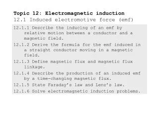
EMF induced
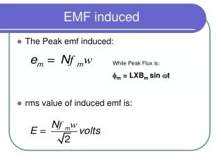
EMF induced. The Peak emf induced: rms value of induced emf is:. While Peak Flux is: m = LXB m sin t. Change in Flux. The change in the flux linkage can be brought about in a variety of ways: coil may be static and unmoving but the flux linking the same may change with time

EMF induced
E N D
Presentation Transcript
EMF induced • The Peak emf induced: • rms value of induced emf is: While Peak Flux is: m= LXBm sin t
Change in Flux The change in the flux linkage can be brought about in a variety of ways: • coil may be static and unmoving but the flux linking the same may change with time • flux lines may be constant and not changing in time but the coil may move in space linking different value of flux with time. • both 1 and 2 above may take place. The flux lines may change in time with coil moving in space.
LHR In the case of electric machines, circuits in relative motion are magnetically coupled for the purpose of transferring energy between mechanical and electrical systems. Because magnetically coupled circuits play such an important role in power transmission and conversion, it is important to establish the equations that describe their behavior and to express these equations in a form convenient for analysis.
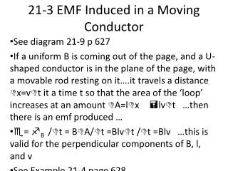
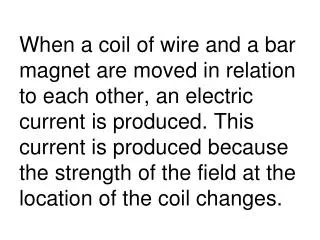
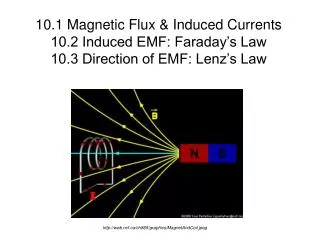
Generating Fig. 2 shows a region of length L m, of uniform flux density B Tesla, the flux lines being normal to the plane of the paper. A loop of one turn links part of this flux. The flux linked by the turn is L B X Weber. Here X is the length of overlap in meters as shown in the figure. If now B does not change with time and the loop is unmoving then no emf is induced in the coil as the flux linkages do not change. Such a condition does not yield any useful machine. On the other hand if the value of B varies with time a voltage is induced in the coil linking the same coil even if the coil does not move.
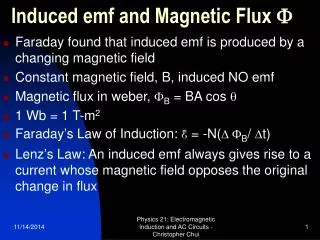
Change in Flux Linkage The magnitude of B is assumed to be varying sinusoidal, and can be expressed as: • Where • Bm is the peak amplitude of the flux density. is the angular rate of change with time. Then, the instantaneous value of the flux linkage is given by: • = N = NLXBm sin t Which of electrical machine that is applicable?
Rate of change of Flux Linkage • Instantaneous flux: Moving Coil • Instantaneous emf :
Matlab Flux & EMF % flaux and emf connectin Emf.m N=200; L=0.2; x=0.02; Bm=50; w=314.2; t=[0.0:0.001:0.02]; flux=N*L*x*Bm*sin(w*t); e=N*L*x*Bm*w*cos(w*t); plot(t, flux*314,t,e)