EMF
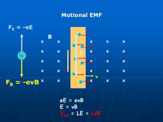
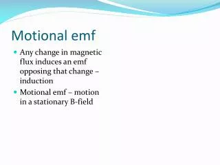
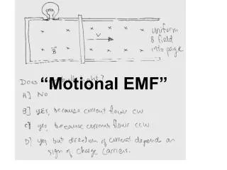
When a wire is moved in a magnetic field, there is an electric current in the wire, but only while the wire is moving. The direction of the current depends on the direction in which the wire is moving through the field. The arrows indicate the direction of conventional current.

EMF
E N D
Presentation Transcript
When a wire is moved in a magnetic field, there is an electric current in the wire, but only while the wire is moving. The direction of the current depends on the direction in which the wire is moving through the field. The arrows indicate the direction of conventional current.
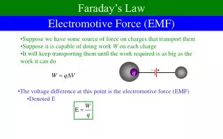
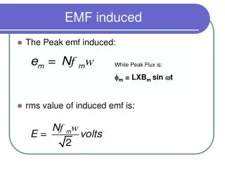
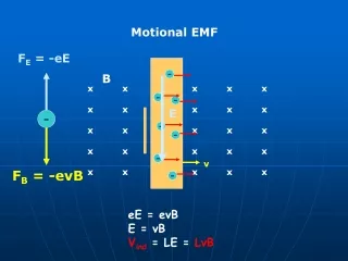
Electromotive Force, or EMF. Electromotive force, however, is not actually a force; instead, it is a potential difference and is measured in volts. Thus, the term electromotive force is misleading. Like many other historical terms still in use, it originated before the related principles—in this case, those of electricity—were well understood. The EMF is the influence that makes current flow from lower to higher potential, like a water pump in a water fountain. EMF
In this drawing of a moving coil microphone, the aluminum diaphragm is connected to a coil in a magnetic field. When sound waves vibrate the diaphragm, the coil moves in the magnetic field and generates a current that is proportional to the sound wave.
Electric Generators The electric generator, invented by Michael Faraday, converts mechanical energy to electrical energy. An electric generator consists of a number of wire loops placed in a strong magnetic field. The wire is wound around an iron core to increase the strength of the magnetic field. The iron and wires are called the armature, which is similar to that of an electric motor. Animations
The armature is mounted so that it can rotate freely in the magnetic field. As the armature turns, the wire loops cut through the magnetic field lines and induce an EMF. • Commonly called the voltage, the EMF developed by the generator depends on the length of wire rotating in the field. Increasing the number of loops in the armature increases the wire length, thereby increasing the induced EMF. • Note that you could have a length of wire with only part of it in the magnetic field. Only the portion within the magnetic field induces an EMF.
The cross-sectional view of a rotating wire loop shows the position of the loop when maximum current is generated (a). When the loop is vertical, the current is zero (b). The current varies with time as the loop rotates (c). The variation of EMF with time can be shown with a similar graph.
Sincethe conducting loop is rotating in a circular motion, the relative angle between a point on the loop and the magnetic field constantly changes. The electromotive force can be calculated by the electromotive force equation given earlier, EMF = BLv (sin θ), except that L is now the length of segment bc. The maximum voltage is induced when a conductor is moving perpendicular to the magnetic field and thus θ= 90°.
An alternating-current generator transmits current to an external circuit by way of a brush - slip-ring arrangement (a). The alternating current produced varies with time (b). The resulting power is always positive and also is sinusoidal (c).
Effective voltage and current : It is common to describe alternating current and voltage in terms of effective current and voltage, rather than referring to their maximum values. Recall from Chapter 22 that P = I2R.
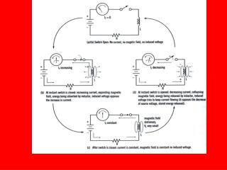
Lenz’s Law… Lenz's law A law of electromagnetism which states that, whenever there is an induced electromotive force (emf) in a conductor, it is always in such a direction that the current it would produce would oppose the change which causes the induced emf. If the change is the motion of a conductor through a magnetic field, the induced current must be in such a direction as to produce a force opposing the motion. If the change causing the emf is a change of flux threading a coil, the induced current must produce a flux in such a direction as to oppose the change. Huh??
A wire, length L, moving through a magnetic field, B, induces an electromotive force. If the wire is part of a circuit, then there will be a current, I. This current will interact with the magnetic field and produce a force, F. Notice that the resulting force opposes the motion, v, of the wire.
Magnetic field resulting from induced current Note that this loop must form a complete circuit! The magnet approaching the coil causes an induced current to flow. Lenz’s law predicts the direction of flow shown.
Current (and thus an opposing magnetic field) is induced in the continuous metal ring, while there is no current in the cut ring.
Sensitive balances use eddy-current damping to control oscillations of the balance beam (a). As the metal plate on the end of the beam moves through the magnetic field, a current is generated in the metal. This current, in turn, produces a magnetic field that opposes the motion that caused it, and the motion of the beam is dampened (b).
How transformers work Self-inductance produces an EMF when current changes in a single coil. A transformer has two coils, electrically insulated from each other, but wound around the same iron core. One coil is called the primary coil. The other coil is called the secondary coil. When the primary coil is connected to a source of AC voltage, the changing current creates a changing magnetic field, which is carried through the core to the secondary coil. In the secondary coil, the changing field induces a varying EMF. This effect is called mutual inductance. Web link
P=IV applies on BOTH SIDES. A transformer does not produce “free” voltage or power!
If the secondary voltage is larger than the primary voltage, the transformer is called a step-up transformer. .If the voltage coming out of the transformer is smaller than the voltage put in, then it is called a step-down transformer.
Everyday uses of transformers As you learned in Chapter 22, long-distance transmission of electrical energy is economical only if low currents and very high voltages are used. Step-up transformers are used at power sources to develop voltages as high as 480,000 V. High voltages reduce the current required in the transmission lines, keeping the energy lost to resistance low. When the energy reaches the consumer, step-down transformers, such as those shown, provide appropriately low voltages for consumer use.