Download
1 / 37
400 likes | 597 Vues
This document provides a comprehensive overview of counter EMF (Back EMF) in inductors, emphasizing its significance when current changes in a DC circuit. It explains how induced voltage opposes the original voltage according to Lenz's law, exploring the relationship between inductance, coil design, and the magnetic field. The document also presents calculations for inductance using the formula L = (μN²A)/l, along with examples illustrating induced voltage and total inductance in circuits. A perfect resource for students and engineers seeking to grasp the principles of electromagnetism.

E N D
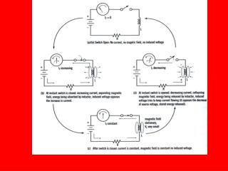
Counter EMF (also known as Back EMF) When the current through an inductor changes, the magnetic field also changes. This changing magnetic field causes there to be an induced voltage across the terminals of the inductor. This induced voltage’s polarity is in a direction opposite to that of the original voltage applied. This is basically Lenz’s law in a nutshell.
Current through inductors in a DC circuit when switch closes
What do you think voltage across an inductor looks like in a DC circuit when the switch is closed?
Voltage through inductors in a DC circuit when switch closes Inductance has it greatest effect only when there is a change in current.
Inductance Summary Inductors react against changes in current by dropping voltage in a polarity necessary to oppose the change When an inductor is faced with an increasing current, it acts as a load, by dropping voltage. (series opposing) When an inductor is faced with a decreasing current, it acts as a source, by dropping voltage. (series aiding) The ability of an inductor to store energy in the form of a magnetic field (and consequently opposing changes in current) is called inductance. The unit of inductance is the Henry – H (Denoted as the letter L on a schematic)
Inductor Schematic Symbol Typically, the range of inductors are from micro-Henry’s to milli-Henry’s (H to mH)
In the picture of the inductor below, since current takes the path of least resistance, why wouldn’t the current just bypass all the turning and jump straight across the tops of all the coils? Because there is a clearenamel coating on the wires that acts like an insulator
18.3 Inductance Factors Affecting Coil Inductance
The design of the inductor is most important in determining the value of inductance. 1. The amount of turns in creating the coil affect how much voltage can be linked between the turns. In a later equation, this figure is denoted by (N). Factors Affecting Coil Inductance N
2. The diameter of the coil affects inductance. A larger diameter core results in more magnetic lines of force than compared to a smaller diameter coil. Denoted by (A) for area=πr2. Coil Inductance Factors (cont.) A r
3. As the length (l) of the inductor grows, the distance between turns increases, which causes the magnetic field to get weaker. Denoted by l, for length in meters, not I for current! Coil Inductance Factors (cont.) l l
Coil Inductance Factors (cont.) µ • 4. And finally, inductance is affected by the core material in which the coil is wrapped around. Higher permeability enables more flux to form. More flux means more inductance. This is denoted by (µ) pronounced “mju”, not known as micro in this case.
Inductance equation18.3.1 L= µN2A l L= Inductance in Henrys, H µ=permeability of core, µ0µr µ0= 1.26 x 10⁻⁶ (The absolute permeability of air) µr= relative permeability of core material, refer to Table 16.2 N= number of coil turns A= area of cross-section of coil wire, πr2. l= length of core material (m)
Inductance problem worked out • Given: l=10cm r=1.5cm N=200 turns l= .1m r=.015m N=200 turns It’s an air core that we’re dealing with. So relative permeability is µr =1. L= (µ0µr)(200)2[π(.0152)] .1 L= µN2A l L= [(1.26 x 10⁻⁶)(1)](40000)(.000707) .1 L= .000035632 .1 L= .00035632 H or 356.3 µH
Another Inductance problem! • Given: l=15cm r=.02m N=500 turns Machine Steel Core • Find Inductance Value
Another Inductance problem! • Given: l = 15cm r = .02m L = 3mH Nickel Core • Find the number of turns
Measuring the induced voltage across an inductor • Equation 18.1: This equation says that the higher the change in current, and the faster that change occurs, the higher the voltage across the inductor will be.
How much self-induced voltage occurs across a 4H inductor when the current going through it changes by 10Amps in 1 second?
How much self-induced voltage occurs across a 4mH inductor when the current going through it changes by 10Amps in 1ms? 1ms) = 400V
Calculating total inductance LT • What is the total inductance of this circuit? 62H Calculating the total inductance in a circuit is done the same way as calculating the total resistance
Calculating total inductance LT • What is the total inductance of this circuit? 6H Calculating the total inductance in a circuit is done the same way as calculating the total resistance
Calculating total inductance LT • What is the total inductance of this circuit? LT = 15H Calculating the total inductance in a circuit is done the same way as calculating the total resistance
However! There is a subtle difference in calculating LT that you don’t have to consider when calculating RT • What if the magnetic field from one inductor interferes with the magnetic field from the inductor next to it? • In other words, if the magnetic field from one inductor cuts the across the coils of the inductor located physically next to it, then extra inductance will be introduced, (or some inductance will be cancelled out.) THIS IS CALLED MUTUAL INDUCTANCE
Calculating total inductance if there is mutual inductance involved • In the circuit above, if the inductor’s magnetic fields didn’t interfere with each other, aka have no mutual inductance, then the total inductance is just 13H. • However, suppose the inductors magnetic fields were completely overlapping each other, then we would have to consider this.
k is the coefficient of coupling and it is a number ranging from 0% to 100% • If the coils of 2 inductors were wrapped around each other, then the magnetic fields of each have no choice but to couple themselves to the other inductor. • In this case the coefficient of coupling, k, is 100%. • If the inductors’ magnetic fields are not coupled, then k = 0.
MUTUAL INDUCTANCE k = .9 k = .3 k = 0
Calculating total inductance if there is mutual inductance involved • Suppose the inductors were connected in a series aiding arrangement with a coefficient of coupling of 90%.
Calculating total inductance if there is mutual inductance involved • Suppose the inductors were connected in a series opposing arrangement with a coefficient of coupling of 90%.
2 coils have inductances of 8mH and 4.7mH. If the coefficient of coupling between them is .82, what is the mutual inductance? LT = 8mH + 4.7 mH + 5.03mH = 17.73mH (If in series aiding arrangement) LT = 8mH + 4.7 mH - 5.03mH = 7.67mH (If in series opposing arrangement)
Types of Inductors • Put table from lecture notes here
Stray Inductance • Talk about stray inductance