Motional EMF
220 likes | 391 Vues
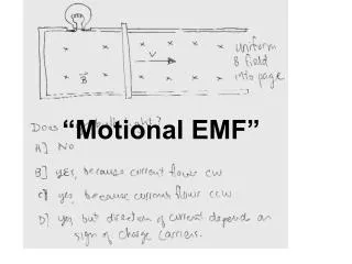
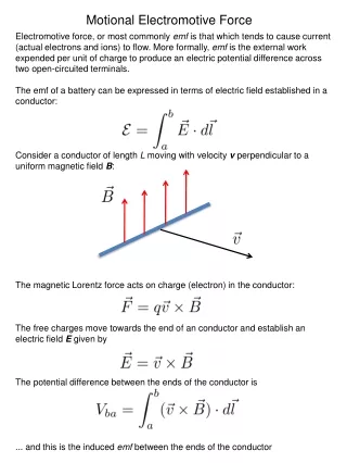
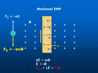
F E = -eE. E. -. v. F B = -evB. Motional EMF. B. -. x x x x x x x x x x x x x x x x x x x x x x x x x x x x x x. -. -. -. -. -. -. eE = evB E = vB V ind = LE = LvB. v. V d t. x x x x x x x x x x x x x x x x x x x x x x x x x x x x x x. L. d.

Motional EMF
E N D
Presentation Transcript
FE = -eE E - v FB = -evB Motional EMF B - x x x x x x x x x x x x x x x x x x x x x x x x x x x x x x - - - - - - eE = evB E = vB Vind = LE = LvB
v V dt x x x x x x x x x x x x x x x x x x x x x x x x x x x x x x L d Fi = LdB Ff = L(d+vdt)B |Vind |= dF/dt = LvdtB/dt = LvB
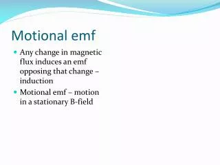
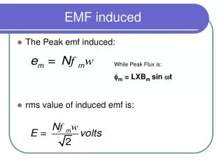
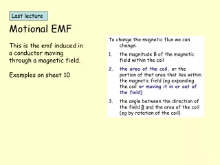
Motional emf • As the negative charges accumulate at the base, a net positive charge exists at the upper end of the conductor • As a result of this charge separation, an electric field is produced in the conductor • Charges build up at the ends of the conductor until the downward magnetic force is balanced by the upward electric force • There is a potential difference between the upper and lower ends of the conductor
Motional emf, cont • The potential difference between the ends of the conductor can be found by • V = B v L • The upper end is at a higher potential than the lower end • A potential difference is maintained across the conductor as long as there is motion through the field • If the motion is reversed, the polarity of the potential difference is also reversed
Motional emf in a Circuit • Assume the moving bar has zero resistance • As the bar is pulled to the right with velocity v under the influence of an applied force, F, the free charges experience a magnetic force along the length of the bar • This force sets up an induced current because the charges are free to move in the closed path
Motional emf in a Circuit, cont • The changing magnetic flux through the loop and the corresponding induced emf in the bar result from the change in area of the loop • The induced, motional emf, acts like a battery in the circuit
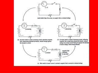
Lenz’ Law Revisited – Moving Bar Example • As the bar moves to the right, the magnetic flux through the circuit increases with time because the area of the loop increases • The induced current must in a direction such that it opposes the change in the external magnetic flux
Lenz’ Law, Bar Example, cont • The flux due to the external field in increasing into the page • The flux due to the induced current must be out of the page • Therefore the current must be counterclockwise when the bar moves to the right
Lenz’ Law, Bar Example, final • The bar is moving toward the left • The magnetic flux through the loop is decreasing with time • The induced current must be clockwise to to produce its own flux into the page
Lenz’ Law, Moving Magnet Example • A bar magnet is moved to the right toward a stationary loop of wire (a) • As the magnet moves, the magnetic flux increases with time • The induced current produces a flux to the left, so the current is in the direction shown (b)
Lenz’ Law, Final Note • When applying Lenz’ Law, there are two magnetic fields to consider • The external changing magnetic field that induces the current in the loop • The magnetic field produced by the current in the loop
Generators • Alternating Current (AC) generator • Converts mechanical energy to electrical energy • Consists of a wire loop rotated by some external means • There are a variety of sources that can supply the energy to rotate the loop • These may include falling water, heat by burning coal to produce steam
AC Generators, cont • Basic operation of the generator • As the loop rotates, the magnetic flux through it changes with time • This induces an emf and a current in the external circuit • The ends of the loop are connected to slip rings that rotate with the loop • Connections to the external circuit are made by stationary brushed in contact with the slip rings
AC Generators, final • The emf generated by the rotating loop can be found by V =2 B ℓ v=2 Bℓ v sin θ • If the loop rotates with a constant angular speed, ω, and N turns V = N B A ω cos ω t • V = Vmax when loop is parallel to the field • V = 0 when when the loop is perpendicular to the field
AC Generator http://hyperphysics.phy-astr.gsu.edu/hbase/magnetic/motorac.html#c2
Angular velocity, w: Amount of angle (radian) turned in a second wt = total angle of turn during time t 2pf = w period T = 1/f = 2p/w t = 0: = 0 t = t1: = A B sin(wt1) wt1 Vind = - d/dt = - ABsin(wt1)/t1 Vind = - /t = - ABwcos(wt) AC generation
Neutral Hot GND http://www.howstuffworks.com/
170 V -170 V When we say 120 V, it means rms value!! P v2 or i2 vrms = 0.707va
Power Transmission City of Gainesville has 120,000 population. On average approximately 200 W/person of electric power is required. Let’s assume that GRU transmit power with 120 V. How much current Should be carried in power line? Pt = 120,000 x 200 W = 24,000,000 W = 24 MW P = IV, I = P/V = 24,000,000/120 = 200,000 A However, if we deliver power with 500,000 V, I = 24,000,000/500,000 = 48 A Now Joule heating due to wire resistance (R) is reduced By (48/200,000)2 = 5.8 x 10⁻⁸
Transformer Iron Core V AC dF/dt Vp = -NpdF/dt Vs = -NsdF/dt Np Ns Vp/Vs = Np/Ns