Internet Protocol (IP)
Internet Protocol (IP). Raj Jain The Ohio State University Columbus, OH 43210 Jain@cse.ohio-State.Edu http://www.cse.ohio-state.edu/~jain/. Internetworking IP Address format IP data forwarding Fragmentation and reassembly


Internet Protocol (IP)
E N D
Presentation Transcript
Internet Protocol (IP) Raj Jain The Ohio State UniversityColumbus, OH 43210Jain@cse.ohio-State.Edu http://www.cse.ohio-state.edu/~jain/
Internetworking • IP Address format • IP data forwarding • Fragmentation and reassembly Ref: Chapters 13, 14, 16, and 17 of Comer’s Computer Networks and Internets Overview
Internetworking • Internetwork = Collection of networks Connected via routers Network Network Router Fig 13.1
Internet = Virtual Network • Any computer can talk to any other computer Net 2 Net 3 Net 1 Net 4 Fig 13.3
0 Network Local 1 7 24 bits • Class C:(3+1 bytes) 110 Network Local 3 21 8 bits IP Address • Class A:(1+3 bytes) • Class B:(2+2 bytes) 10 Network Local 2 14 16 bits • Class D: 1110 Host Group (Multicast) 4 28 bits • Local = Subnet + Host (Variable length) Router Router Subnet
First 4 bits Index Class 0000 0 A 0001 1 A 0010 2 A 0011 3 A 0100 4 A 0101 5 A 0110 6 A 0111 7 A 1000 8 B 1001 9 B 1010 10 B 1011 11 B 1100 12 C 1101 13 C 1110 14 D 1111 15 E Computing The Class of an Address
Class Range A 0 through 127 B 128 through 191 C 192 through 223 D 224 through 239 E 240 through 255 Classes and Dotted Decimal Notation • Binary: 11000000 00000101 00110000 00000011Hex Colon: C0:05:30:03 Dotted Decimal: 192.5.48.3 Fig 14.4
Class Bits in Max # of Bits in Max # of Hosts Prefix Nets Suffix per Net A 7 128 24 16,777,216 B 14 16,384 16 65,536 C 21 2,097,152 8 256 Division of the Address Space • Not all possible addresses can be used. Fig 14.5
An Addressing Example Router • All hosts on a network have the same network prefix 128.10 128.211 Router 128.10.0.1 128.10.0.2 128.211.6.115 10.0.0.37 10.0.0.49 192.5.48.3 10 Router 192.5.48 Fig 14.6
Subnetting • With classes, the network part is 1-byte, 2-byte, or 3-byte long. You need class B address space just for 257 addresses. • Any number of bits can be treated as one “subnetwork” • Example: First 23 bits = subnetAddress: 10010100 10101000 00010000 11110001Mask: 11111111 11111111 11111110 00000000.AND. 10010100 10101000 00010000 00000000 Network Subnet 1 Subnet 2 Subnet n
Supernetting • Subnetting = subset of a network • Supernet = superset of networks = S Class C addresses • Example: Class C 1: 11010100 10101000 00010000Class C 2:11010100 10101000 00010001Supernet: 11010100 10101000 0001000 • First 23 bits = subnetAddress: 11010100 10101000 00010001 11110001Mask: 11111111 11111111 11111110 00000000.AND. 10010100 10101000 00010000 00000000
Special IP Addresses • All-0 host suffix Network Address • All-0s This computer(In some old networks: 0.0.0.0 = broadcast. Not used.) • All-0s network This network. E.g., 0.0.0.2 = Host 2 on this network • All-1 host suffix All hosts on the destination net (directed broadcast), All-0 host suffix Berkeley directed broadcast address • All-1s All hosts on this net (limited broadcast) Subnet number cannot be all 1 • 127.*.*.* Looback through IP layer
Private Addresses • Any organization can use these inside their networkCan’t go on the internet. [RFC 1918] • 10.0.0.0 - 10.255.255.255 (10/8 prefix) • 172.16.0.0 - 172.31.255.255 (172.16/12 prefix) • 192.168.0.0 - 192.168.255.255 (192.168/16 prefix) Internet PrivateNetwork NetworkAddressTranslator PrivateAddresses PublicAddresses
Classless Interdomain Routing (CIDR) • Pronounced “Cider” • Classless Þ Forget classes. Use Addresses and prefix lengths [RFC1517-1520] • All routing table entries have prefix lengthsExample: 164.107.61.0/26
Multi-Homed Hosts • Each interface has an address.Two or more interfaces Multi-homed hosts • Multihoming is for reliability or performance Host R1 R2 Interfaces
Routers and the IP Addressing Principle • Routers have two or more addresses. One for each interface. Ethernet131.108.0.0 131.108.99.5 Token Ring223.240.129.0 Router 223.24.129.2 223.240.129.17 WAN 78.0.0.0 Router 78.0.0.17 Fig 14.8
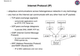
IP Features • Connectionless service • Variable size datagrams • Best-effort delivery: Delay, out-of-order, corruption, and loss possible. Higher layers should handle these. • Handles only data forwardingUses routing tables prepared by other protocols, e.g., Open Shortest Path First (OSPF),Routing Information Protocol (RIP) • Provides only “Send” and “Delivery” servicesError and control messages generated by Internet Control Message Protocol (ICMP)
Net 1 Forward to R1 Net 2 Deliver Direct Net 3 Deliver Direct Net 4 Forward to R3 Forwarding an IP Datagram • Delivers datagrams to destination network (subnet) • Routers maintain a “routing table” of “next hops” • Next Hop field does not appear in the datagram Net 1 Net 2 Net 3 Net 4 R1 R2 R3 Table at R2: Destination Next Hop Fig 16.2
IP Addresses and Routing Table Entries • IF ((Mask[i] & Destination Addr) = = Destination[i]) Forward to NextHop[i] 30.0.0.7 40.0.0.8 128.1.0.9 30.0.0.0 40.0.0.0 128.1.0.0 192.4.0.0 40.0.0.7 128.1.0.8 192.4.10.9 Destination Mask Next Hop 30.0.0.0 255.0.0.0 40.0.0.7 40.0.0.0 255.0.0.0 Deliver direct 128.1.0.0 255.255.0.0 Deliver direct 192.4.10.0 255.255.255.0 128.1.0.9 Fig 16.3
Network-Address Netmask Gateway-Address Interface Metric 0.0.0.0 0.0.0.0 24.93.104.1 24.93.107.238 1 24.93.104.0 255.255.248.0 24.93.107.238 24.93.107.238 1 24.93.107.238 255.255.255.255 127.0.0.1 127.0.0.1 1 24.255.255.255 255.255.255.255 24.93.107.238 24.93.107.238 1 127.0.0.0 255.0.0.0 127.0.0.1 127.0.0.1 1 128.146.0.0 255.255.0.0 164.107.61.254 164.107.61.210 1 164.107.61.0 255.255.255.0 164.107.61.210 164.107.61.210 1 164.107.61.210 255.255.255.255 127.0.0.1 127.0.0.1 1 164.107.255.255 255.255.255.255 164.107.61.210 164.107.61.210 1 224.0.0.0 224.0.0.0 24.93.107.238 24.93.107.238 1 224.0.0.0 224.0.0.0 164.107.61.210 164.107.61.210 1 255.255.255.255 255.255.255.255 164.107.61.210 164.107.61.210 1 Sample Routing Table Router Host Router 164.107.61.254 24.93.104.1 164.107.61.210 24.93.104.238 164.107.61/24 24.93.104/21
Vers H. Len Service Type Total Length Identification Flags Fragment Offset Time to live Type Header Checksum Source IP Address Destination IP Address IP Options (May be omitted) Padding Data IP Datagram Format Fig 16.4
IP Header Format • Version (4 bits) • Internet header length (4 bits): in 32-bit words. Min header is 5 words or 20 bytes. • Type of service (8 bits): Reliability, precedence, delay, and throughput • Total length (16 bits): header + data in bytesTotal must be less than 64 kB. • Identifier (16 bits): Helps uniquely identify the datagram during its life for a given source, destination address
IP Header (Cont) • Flags (3 bits): More flag - used for fragmentation No-fragmentation Reserved • Fragment offset (13 bits): In units of 8 bytes • Time to live (8 bits): Specified in router hops • Protocol (8 bits): Next level protocol to receive the data • Header checksum (16 bits): 1’s complement sum of all 16-bit words in the header
IP Header (Cont) • Source Address (32 bits): Original source. Does not change along the path. • Destination Address (32 bits): Final destination. Does not change along the path. • Options (variable): Security, source route, record route, stream id (used for voice) for reserved resources, timestamp recording • Padding (variable): Makes header length a multiple of 4 • Data (variable): Data + header < 65,535 bytes
Datagram Datagram Datagram Datagram Datagram Datagram Datagram Transmission Across An Internet Source S • Datalink header changes at every hop Datalink header Net 1 Header 1 IP header R1 Net 2 Header 2 R2 Net 3 Header 3 Destination D Fig 17.2
Maximum Transmission Unit • Each subnet has a maximum frame sizeEthernet: 1518 bytesFDDI: 4500 bytesToken Ring: 2 to 4 kB • Transmission Unit = IP datagram (data + header) • Each subnet has a maximum IP datagram length: MTU Net 1MTU=1500 Net 2MTU=1000 R R S Fig 17.3
Decimal Key word Protocol 0 Reserved 1 ICMP Internet Control Message Protocol 2 IGMP Internet Group Management Protocol 4 ST Stream Protocol 5 TCP Transmission Control Protocol 8 EGP Exterior Gateway Protocol 9 IGP Interior Gateway Protocol 17 UDP User Datagram Protocol IP Protocol Numbers
IP Forwarding Process Packet Received Send ICMP Error Message to source DiscardPacket Header checksum valid? SendARPRequest MAC AddressAvailable? No No Decrement TTLTTL>=0? Yes No ARP ResponseReceived? Yes Build new packetTransmit the packet Route table lookup Yes No No Route found? Default RouteAvailable? Fig 9-2Naugle Yes Yes
IP Options Coding • Flag Copy: 0 = Copy the option only into the first fragment of a fragmented datagram1 = Copy into all fragments • Class: 0 =User or control, 1=Reserved, 2=Diagnostics, 3=reserved Type Length Value 1B 1B nB Flag Copy Class Number 1b 2b 5b
Class Number Length Description 0 0 0 End of Options 0 1 0 No Op 0 2 11 Security 0 3 Var Loose Source Routing 0 7 Var Record Route 0 8 4 Stream ID (obsolete) 0 9 Var Strict Source Routing 4 Var Internet Time-Stamp IP Options 2
IP Source Routing Code Length Pointer Router Data P 128.2.3.4 128.7.8.9 128.10.4.12 P 128.2.3.4 128.7.8.9 128.10.4.12
Route Recording Code Length Pointer Route Data P 128.2.3.4 Empty Empty P 128.2.3.4 128.7.8.9 Empty
Timestamp Option Code Length Pointer Data Oflw Flags IP Address 1 Timestamp 1 IP Address n Timestamp n
Fragmentation • Datagrams larger than MTU are fragmented • Original header is copied to each fragment and then modified (fragment flag, fragment offset, length,...) IP Header Original Datagram IP Hdr 1 Data 1 IP Hdr 2 Data 2 IP Hdr 3 Data 3 Fig 17.4
Fragmentation MTU = 1500B MTU = 512B MTU = 256B ID = 12345, More = 1 Offset = 160W, Len = 1500B ID = 12345, More = 1 Offset = 0W, Len = 512B ID = 12345, More = 1 Offset = 0W, Len = 256B ID = 12345, More = 1 Offset = 32W, Len = 256B ID = 12345, More = 1 Offset = 64W, Len = 512B ID = 12345, More = 1 Offset = 64W, Len = 256B ID = 12345, More = 1 Offset = 96W, Len = 256B ID = 12345, More = 1 Offset = 128W, Len = 476B ID = 12345, More = 1 Offset = 128W, Len = 256B ID = 12345, More = 1 Offset = 160W, Len = 220B
Reassembly • Reassambly only at the final destination • Partial datagrams are discarded after a timeout • Fragments can be further fragmented along the path.Subfragments have a format similar to fragments.It is not possible to tell how many times fragmented. • Minimum MTU along a path Path MTU S D Net 2MTU=1000 Net 1MTU=1500 Net 3MTU=1500 R1 R2 Fig 17.5
Summary • IPv4 uses 32-bit addresses organized as network prefix and host suffix. • Four classes of networks: A, B, C, D • Routers determine next hop using routing tables • IP provides connectionless unreliable service