Stereographic Projection
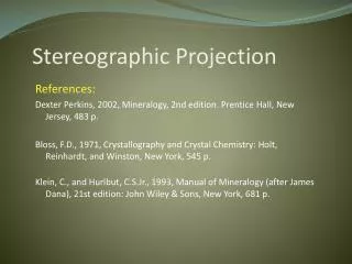
Stereographic Projection. References: Dexter Perkins, 2002, Mineralogy, 2nd edition. Prentice Hall, New Jersey, 483 p. Bloss , F.D., 1971, Crystallography and Crystal Chemistry: Holt, Reinhardt, and Winston, New York, 545 p.

Stereographic Projection
E N D
Presentation Transcript
Stereographic Projection • References: • Dexter Perkins, 2002, Mineralogy, 2nd edition. Prentice Hall, New Jersey, 483 p. • Bloss, F.D., 1971, Crystallography and Crystal Chemistry: Holt, Reinhardt, and Winston, New York, 545 p. • Klein, C., and Hurlbut, C.S.Jr., 1993, Manual of Mineralogy (after James Dana), 21st edition: John Wiley & Sons, New York, 681 p.
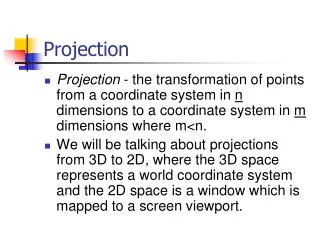
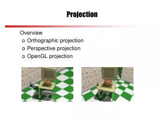
Introduction • Crystals have a set of 3D geometric relationships among their planar and linear features • These include the angle between crystal faces, normal (pole) to these faces, and the line of intersection of these faces • Planar features: crystal faces, mirror planes • Linear features: pole to crystal faces, zone axis, crystal axes • Question: How can we accurately depict all of these planar and linear features on a 2D page and still maintain the correct angular relationships between them? • Answer: With stereographic projection!
Stereographic Projection • Projection of 3D orientation data and symmetry of a crystal into 2D by preserving all the angular relationships • Projection lowers the Euclidian dimension of the object by 1, i.e., planes become lines, and lines become point!
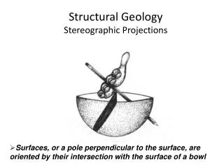
In mineralogy, it involves projection of faces, edges, mirror planes, and rotation axes onto a flat equatorial plane of a sphere, in correct angular relationships • In mineralogy, in contrast to structural geology, stereograms have no geographic significance, and cannot show shape of crystal faces!
Two Types of Stereonet • Wulff net(Equal angle) • Used in mineralogy & structural geology when angles are meant to be preserved • e.g., for crystallography and core analysis • Projection is done onto the upper and lower hemispheres • Schmidt net(Equal area) • Used in structural geology for orientation analysis when area is meant to be preserved for statistical analysis • Uses projection onto the lower hemisphere
Wulffnet forMinerals -90 -135 0 +135 +90
WulffStereonet (Equal Angle net) • Shows the projection of great circles and small circles • Great circle: Line of intersection of a plane, that passes through the center of the sphere, with the surface of the sphere (like lines of longitude on Earth) • NOTE: Angular relationships between points can only be measured on great circles (not along small circles)! • Small circle: Loci of all positions of a point on the surface of the sphere when rotated about an axis such as the North pole (like lines of latitude on Earth)
Why need projection? • Projection of all crystal faces of a crystal leads to many great circles or poles to these great circles • These great circles and poles allow one to determine the exact angular relationship, and symmetry relationships for a crystal • For example, the angle between crystal faces and rotation axes, or between axes and mirror planes • To understand these, we first give an introduction to stereographic projection!
The primitive All great circles go through the N and S poles! Vertical plane Face 1 We commonly plot the poles to these planes as dots Horizontal Plane is the pole (normal) to face 1
Stereographic projection of a line • Each line (e.g., rotation axis, pole to a mirror plane) goes through the center of the stereonet (i.e., the thumb tack) • The line intersects the sphere along the ‘spherical projection of the line’, which is a point • A ray, originating from this point, to the eyes of a viewer located vertically above the center of the net (point O), intersect the ‘primitive’ along one point • The point is the stereographic projection of the line. • A vertical line plots at the center of the net • A horizontal line plots on the primitive
Special cases of lines • Vertical lines (e.g., rotation axes, edges) plot at the center of the equatorial plane • Horizontal lines plot on the primitive • Inclined lines plot between the primitive and the center
Projection of Planar Elements • Crystals have faces and mirror planes which are planes, so they intersect the surface of the sphere along lines • These elements can be represented either as: • Planes, which become great circle after projection • Poles (normals) to the planes, which become points after projection
Stereographic projection of a plane: • Each plane (e.g., mirror plane) goes through the center of the stereonet (i.e., the thumbtack) • The plane intersects the sphere along the ‘spherical projection of the plane’, which is a series of points • Rays, originating from these points, to the eyes of a viewer located vertically above the center of the net (point O), intersect the ‘primitive’ along a great circle • The great circle is the stereographic projection of the plane. The great circle for a: • vertical plane goes through the center • horizontal plane parallels the primitive
http://super.gsnu.ac.kr/lecture/wulff/wulff-1.html Face 2 Face 1 3 2 1 Face 3 pole to the crystal face
Special cases of planes • Stereographic projection of a horizontal face or mirror plane is along the primitive (perimeter) of the equatorial plane • Stereographic projection of a vertical face or mirror plane is along the diameters of the equatorial plane • They pass through the center • They are straight ‘great circles’ • Inclined faces and mirror planes plot along curved great circles that do not pass through the center
Preparing to plot • Mark N of the net as -90, E as 0, S as =+90 )(for ). • Mount the stereonet on a cardboard. Laminate it. Pass a thumbtack through the center from behind the board • Secure the thumbtack with a masking tape from behind the cardboard • Place a sheet of tracing paper on the stereonet • Put a scotch tape at the center, from both sides of the tracing paper; pierce the paper through the pin • Tracing paper can now rotate around the thumbtack without enlarging the hole (because of scotch tape)
-90 http://super.gsnu.ac.kr/lecture/wulff/wulff-1.html -135 00 +135 +90
Symbols used • For faces below the equator (when using lower hemisphere), place an open circle symbol () where the ray connecting the spherical projection of the pole to the plane intersects the equatorial plane • This is the stereographic projection of the pole to the face • For faces above the equator (when using the upper hemisphere), place a solid circle symbol () the ray connecting the spherical projection of the pole to the plane intersects the equatorial plane • Use a bull’s-eye symbol () to show a point above the page that coincides with one directly below it (using both hemispheres) • Reorient the stereogram such that lines of symmetry are north-south or east-west
Projection of Linear Elements • We can show all of the symmetry elements of a crystal and their relative positions stereographically • Edges, pole to crystal faces, and rotation or rotoinversion axes are lines • When extended through the origin of the sphere, lines intersect the surface of the sphere as points • Each of these points, when connected to the upper or lower pole of the sphere (viewer’s eyes), is projected onto the equatorial plane, and depicted as a polygonsymbol with the same number of sides as the ‘fold’ of the axis
Mirror and Polygon Symbols To plot symmetry axes on the stereonet, use the following symbol conventions: Mirror plane: ― (solid line great circles) Lines:
Plotting the rotation axes • Vertical axes (normal to page) will only have one polygon symbol • Horizontal axes (in the plane of page) intersect the primitive twice, hence they have two polygons • Inclined axes will have one polygon symbol • An open circle in the middle of the polygon shows there is a center of symmetry
Measuring angle between faces • This is done using the poles to the faces! • Three cases: • On the primitive, the angle is read directly on the circumference of the net • On a diameter, the paper is rotated until the zone is coincident with the vertical diameter (i.e., N-S or E-W) and the angle measured by the diameter • On a great circle (an inclined zone), rotate the paper until the zone coincides with a great circle on the net; read the angle along the great circle
Going from one hemisphere to another • During rotation of the pole to a face by a certain angle, we may reach the primitive before we are finished with the amount (angle) of rotation • In this case we are moving from one hemisphere to another • Move the pole back away from the primitive along that same small circle you followed out to the primitive, until it has been moved the correct total number of degrees • Then note its new position with the point symbol for the new hemisphere
How to find reflection of a point • Having a symmetry (mirror) plane and a point p, find the reflection of point p (i.e., p’) across the mirror: • Align the mirror along a great circle • Rotate point p along a small circle to the mirror plane • Count an equal angle beyond the mirror plane, on the same small circle, to find point p’ • If the primitive is reached before p’, then count inward along the same great circle
Crystallographic Angles • Interfacial angle: between two crystal faces is the angle between poles to the two faces. • The interfacial angle can be measured with a contact goniometer • These angles are plotted on the stereonet
Making a stereographic projection of a crystal face pole Use a contact goniometer to measure the interfacial angles (also measures poles)
Convention • By convention (Klein and Hurlbut, p.62), we place the crystal at the center of the sphere such that the: • c-axis (normal of face 001) is the vertical axis • b-axis (normal of face 010) is east-west • a-axis (normal of face 100) is north-south • See next slide!
http://www.tulane.edu/~sanelson/eens211/stereographic_projections.htmhttp://www.tulane.edu/~sanelson/eens211/stereographic_projections.htm axis axis a axis
The ρ and φ angles • Generally, it is the angles of the spherical projection, ρ and φ, that are given for each face of a crystal • These are measured with goniometer • If these are known, then the actual angles between any two faces can easily be obtained through trigonometry, or by the use of the stereonet
The ρ angle • The ρ angle, is between the c axis and the pole to the crystal face, measured downward from the North pole of the sphere • A crystal face has a ρ angle measured in the vertical plane containing the axis of the sphere and the face pole. • Note: the (010) face has a ρ angle of 90o • The φ angle is measured in the horizontal equatorial plane. • Note: the (010) face has a φ angle of 0o!
Plotting ρ and φ Suppose you measured ρ= 60o and φ= 30o for a face with goniometer. Plot the pole to this face on the stereonet. Procedure: Line up the N of the tracing paper with the N of the net. From E, count 30 clockwise, put an x. Bring x to the E, and then count 60 from the center toward E, along the E-W line. Mark the point with . NOTE: The origin for the φ angle is at E (i.e., φ =0). -φ is counted counterclockwise, horizontally from E to the N on the primitive. +φ is counted clockwise horizontally from E to S (i.e., clockwise) on the primitive.
http://www.tulane.edu/~sanelson/eens211/stereographic_projections.htmhttp://www.tulane.edu/~sanelson/eens211/stereographic_projections.htm These angular measurements are similar to those we use for latitude and longitude to plot positions of points on the Earth's surface For the Earth, longitude is similar to the φ angle, except longitude is measured from the Greenwich Meridian, defined as φ = 0o Latitude is measured in the vertical plane, up from the equator, shown as the angle θ. Thus, the ρ angle is like what is called the colatitude (90o - latitude).
Zone plotting • Zone: Two or more faces whose edges of intersection are parallel to a specific linear direction in a crystal • This direction is called the zone axis. A zone is indicated by a symbol similar to that for the Miller Indices of faces, the generalized expression for a zone is [uvw], e.g., all faces parallel to the c axis in an orthorhombic crystal are said to lie in the [001] zone • All faces in a zone lie on a great circle; i.e., a zone is constructed by aligning the poles to these faces on a great circle • The zone axis (pole to the zone) is normal (i.e., 90o) to this great circle • On the stereogram, the lower hemisphere part of the zone great circle is dashed, while the upper great circle is solid • Lower-hemisphere faces are depicted by open circle symbol () • Upper hemisphere faces are depicted by filled circle symbol ()
(111) (100) (111) (011) (100) all coplanar (= zone) Thus all poles in a zone are on the same great circle
The following rules are applied: • All crystal faces are plotted as poles (lines perpendicular to the crystal face. Thus, angles between crystal faces are really angles between poles to crystal faces • The b crystallographic axis is taken as the starting point. Such an axis will be perpendicular to the (010) crystal face in any crystal system. The [010] axis (note the zone symbol) or (010) crystal face will therefore plot at φ = 0o and ρ = 90o • Positive φ angles will be measured clockwise on the stereonet, and negative φ angles will be measured counter-clockwise on the stereonet
Rules cont’d • Crystal faces that are on the top of the crystal (ρ< 90o) will be plotted with the closed circles () symbol, and crystal faces on the bottom of the crystal (ρ > 90o) will be plotted with the "" symbol • Place a sheet of tracing paper on the stereonet and trace the outermost great circle. Make a reference mark on the right side of the circle (East) • To plot a face, first measure the φ angle along the outermost great circle, and make a mark on your tracing paper. Next rotate the tracing paper so that the mark lies at the end of the E-W axis of the stereonet
Rules cont’d • Measure the ρ angle out from the center of the stereonet along the E-W axis of the stereonet • Note that angles can only be measured along great circles. These include the primitive circle, and the E-W and N-S axis of the stereonet • Any two faces on the same great circle are in the same zone. Zones can be shown as lines running through the great circle containing faces in that zone • The zone axis can be found by setting two faces in the zone on the same great circle, and counting 90o away from the intersection of the great circle along the E-W axis. • That is, the zone axis is the pole to the great circle of the poles to the faces in a zone
http://www.tulane.edu/~sanelson/eens211/stereographic_projections.htmhttp://www.tulane.edu/~sanelson/eens211/stereographic_projections.htm As an example, the ρ and φ angles for the (111) crystal face in a crystal model is shown hereNote again that the ρ angle is measured in the vertical plane containing the c axis and the pole to the face, and the φ angle is measured in the horizontal plane, clockwise from the b axis.
Fig 6.3 D and E are spherical projections, i.e., where the pole to the faces intersect the inside of the sphere D' and E' are stereographic projections, when DS and ES intersect the equator (when projected to the south pole) Distance GD' = f(ρ) as ρ 90 D’ G as ρ 0 D’ O We are looking along the primitive, and viewer’s eye is at the S pole for the two shown faces. The upper an lower hemisphere shown!
Examplefor an isometric crystal a3 axis See the isometric crystal axes in the next slide! NOTE: This is a 3D view! a2 axis a1 axis The stereonet is the equatorial plane of the sphere!
Upper hemisphere stereographic projection of the poles to the upper crystal faces are shown by the () symbolsViewer’s eyes are at the south pole Stereographic projection of the isometric crystal in the previous slide
Symmetry elements of an isometric crystal. Legend • Pole to the upper () • and lower () crystal faces
Stereographic projection of an isometric crystal NOTE: ρis measured as the distance (in o) from the center of the projection to the position where the pole to the crystal face plotsφis measured around the circumference of the circle, in a clockwise direction away from the b crystallographic axis (010)
(1-00) (1-10) (1-1-0) (1-01) (1-11) (1-1-1) (010) (001) a2 axis (01-1) (011) a3 (01-0) =45o (111) =45o (11-1) (101) =90o (110) (11-0) (100) a1axis
Explanation of Previous Slide • In the previous slide, only the upper faces of an isometric crystal are plotted. These faces belong to forms {100}, {110}, and {111} • Form: set of identical faces related by the rotational symmetry (shown by poles/dots in stereograms) • Faces (111) and (110) both have a φ angle of 45o • The ρ angle for these faces is measured along a line from the center of the stereonet (where the (001) face plots) toward the primitive. For the (111) face the ρ angle is 45o, and for the (110) face the ρ angle is 90o
As an example all of the faces, both upper and lower, are drawn for a crystal in the class 4/m 2/m in the forms {100} (hexahedron - 6 faces), {110} (dodecahedron, 12 faces), and {111} (octahedron, 8 faces) in the stereogram to the rightRotation axes are indicated by the symbols as discussed aboveMirror planes are shown as solid lines and curves, and the primitive circle represents a mirror plane. Note how the symmetry of the crystal can easily be observed in the stereogram http://www.tulane.edu/~sanelson/eens211/stereographic_projections.htm