05 - Wiring Methods and Practices
05 - Wiring Methods and Practices. The intent of this presentation is to present enough information to provide the reader with a fundamental knowledge of the wiring methods and practices used within Michelin and to better understand basic system and equipment operations.

05 - Wiring Methods and Practices
E N D
Presentation Transcript
The intent of this presentation is to present enough information to provide the reader with a fundamental knowledge of the wiring methods and practices used within Michelin and to better understand basic system and equipment operations.
05 - Wiring Methods and Practices Wiring Practices Terminal blocks shall be wired and mounted so the internal and external wiring does not cross over the terminals. No more than one conductor shall be terminated at each terminal block connection. Terminal blocks should be numbered in numerical ascending order from left to right. Terminal blocks for power circuits shall be grouped separately from control circuits. Conductors and cables shall be run from terminal to terminal without splices or joints. There should be no exposed live parts when the disconnecting means is in the open position. Alternating current (AC) control voltage shall be 120 volts or less, single phase. Grounded control circuits only shall be permitted.
05 - Wiring Methods and Practices Wiring Practices Terminal X2 shall be connected to the grounding conductor. Ground faults on any control circuit shall not cause unintentional starting or dangerous movements, or prevent stopping of the machine A Neutral Link shall be inserted between X2 and wire # 2. Ring connectors shall be used to connect conductors to non-captive type terminals. Cable ends shall be used on each conductor attached to a terminal strip (power or control) and any other connections that are captive. All grounding conductors shall be terminated individually on the ground bar, using tapped connections. Switch symbols shall be shown on the electrical schematic diagrams with all utilities turned off (electric power, air, water and lubricant), the machine and its electrical equipment in its normal starting conditions. (Home Position)
05 - Wiring Methods and Practices Wiring Practices Symbols for devices shall be identified by a number-letter combination, using designations shown below: Control Relay = *CR Motor Starter = *M Limit Switch = *LS
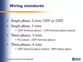
05 - Wiring Methods and Practices Identification of Conductors Conductors shall be identified at each termination by number, letter, color, and shall correspond with the technical documentation. Each conductor shall have the same identification at all terminals and tie points The color GREEN with or without YELLOW stripes shall be used to identify the equipment grounding conductor where insulated or covered. Where an AC circuit includes a grounded conductor (current-carrying) (neutral), this conductor shall be WHITE. Where a DC circuit includes a grounded conductor (current-carrying), this conductor shall be White with Blue stripe. Ungrounded circuit conductors that remain energized when the supply disconnecting means is in the off position shall be consistently applied as either ORANGE or YELLOW.
05 - Wiring Methods and Practices Identification of Conductors The use of other colors for the purpose of identification shall be as follows: BLACK for Line and load circuits, AC or DC 150 volts and above RED for ungrounded AC control conductors less than 150 volts BLUE for ungrounded DC control conductors
05 - Wiring Methods and Practices Identification of Conductors The use of other colors for the purpose of identification shall be as follows: BLACK for Line and load circuits, AC or DC 150 volts and above RED for ungrounded AC control conductors less than 150 volts BLUE for ungrounded DC control conductors Identification of Pushbuttons Stop button operators shall be colored RED and of the extended or unguarded type Start button operators shall be colored BLACK and of the fully guarded type Emergency pushbutton operators shall be of the lock-off (détente) self-latching mushroom operator type. All pushbuttons shall be mounted above or to the left of their associated stop pushbuttons.
05 - Wiring Methods and Practices Conductors Sizes Conductors shall not be smaller than: Power circuits #14 AWG. Control circuits #16 AWG.
05 - Wiring Methods and Practices Electrical Connections
05 - Wiring Methods and Practices Crimping of Connections
05 - Wiring Methods and Practices Conductor Identification
05 - Wiring Methods and Practices Grounding There shall be a connecting bar (ground buss) for all grounding conductors in the circuit. All of the grounding conductors for the inside of the control panel will terminate on the top of the ground buss. All of the grounding conductors for the components outside of the control panel will terminate on the bottom of the ground buss. If the enclosure has a hinged door the continuity of the grounding circuit shall be insured by bonding straps. The secondary of the control transformer (X2) shall be connected directly to the top of the ground buss.
05 - Wiring Methods and Practices Grounding The back plane of the control panel must be bonded to the grounding buss. The din channel for the terminal strip must have an electrical bond to assure that the back plane is at the same potential as ground. This is insured by use of tapped screw connections between the din channel and the backplane. The liaison between the metal frame of all electrical components and the ground circuit must be done with a copper grounding conductor (green or green with a yellow stripe). This applies to the following components: Motor housing ground will be connected inside the terminal box at the motor Pushbutton station enclosures and covers shall be connected as illustrated Limit switch enclosures shall be connected as illustrated
05 - Wiring Methods and Practices Grounding
05 - Wiring Methods and Practices Grounding
05 - Wiring Methods and Practices Lockout/Tagout/Tryout Procedure Purpose and Scope - The purpose of this procedure is to specifically outline the steps to be taken during training with EMI/NA. This procedure is designed for EMI/NA training only and is not intended to be interpreted as the official procedure of any other plant or department. Responsibility - It is the responsibility of the instructors to train all trainees on the lockout procedures. It is the responsibility of the trainees to comply with this procedure when doing any work that involves electrical circuits training or otherwise. Lockout Tags - Lockout tags and locks shall be stored in the individual tool drawers and a responsibility of the trainees. Procedure - The following procedure shall apply to cases where equipment or systems are to be serviced or repaired which will expose personnel to the hazards of moving machinery, energized electrical circuits, or hydraulic/pneumatic circuits. This procedure also applies to electrical training panels and fault finding machines that are not running.
05 - Wiring Methods and Practices Lockout/Tagout/Tryout Procedure Prior to shutting down any equipment, inform the person responsible for that particular area. Trainees shall lock out all necessary systems to make the machine safe. After locking out the main electrical disconnect, the disconnect means shall be tested to ensure that it cannot be moved from the locked position. Verify the meter is operational by testing on a known live circuit Locate and open proper disconnect means for desired circuit Lockout the disconnect means Verify absence of voltage at first entry point on the control panel 3 – phase to phase measurements 3 – phase to ground measurements Try to operate the equipment
05 - Wiring Methods and Practices Lockout/Tagout/Tryout Procedure Distribution Panels - Motors and/or equipment such as lighting and receptacle circuits that are not supplied through safety disconnect switches shall be locked out only by qualified instructors. Special Training Equipment - Equipment that is used for electrical training shall be supplied through a fused disconnect switch. These disconnect switches may only be placed in a "run" condition when trouble-shooting or function tests are being carried out. Removal of Locks - In general, the removal of a lockout lock can only be done by the person who has installed the lock. Note: In the event that a lock has to be cut off because of a lost key, or because the person responsible cannot be reached, approval must be obtained from the electrical instructor before the lock can be removed.