Kinematic Mechanisms: Definitions, Examples, and Degrees of Freedom
Learn about kinematic mechanisms, different types of kinematic pairs, and their roles in forming chains. Explore examples like slider-crank and spatial mechanisms. Understand the concept of degrees of freedom in planar mechanisms.

Kinematic Mechanisms: Definitions, Examples, and Degrees of Freedom
E N D
Presentation Transcript
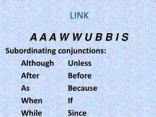
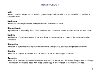
TERMINOLOGY Link A component forming a part of a chain; generally rigid with provision at each end for connection to two other links Mechanism A combination of rigid bodies (links) connected by kinematic pairs. Kinematic pair A joint which is formed by the contact between two bodies and allows relative motion between them. Machine A collection of mechanisms which transmit force from the source of power to the resistance to be overcome Kinematics A branch of dynamics dealing with motion in time and space but disregarding mass and forces Kinetics A branch of physics that deals with the relation of force and changes of motion Dynamics A branch of mechanics that deals with matter (mass) in motion and the forces that produce or change such motion. Mechanics deals with force and energy in their relation to the material bodies.
KINEMATIC PAIR A mechanism is defined as a combination of rigid bodies connected by kinematic pairs. A kinematic pair is a joint which is formed by the contact between two bodies and allows relative motion between them. The contact element on a body, which joins to form a kinematic pair, is called pairing element.
KINEMATIC PAIR Each link in the slider-crank mechanism shown here has two pairing elements.
LOWER KINEMATIC PAIRS • Surface contact pairs are lower pairs. • The commonly used lower pairs include • (1) Revolute Pair • (2) Prismatic Pair • (3) Screw Pair • (4) Cylindrical Pair • (5) Spherical Pair • (6) Planar Pair
REVOLUTE PAIR (PIN JOINT) revolute.SLDASM Degrees of freedom: 1 Symbol: R Relative motion: Circular
PRISMATIC PAIR (SLIDER JOINT) prismatic.SLDASM Degrees of freedom: 1 Symbol: P Relative motion: linear
SCREW PAIR (HELICAL PAIR) screw.SLDASM Degrees of freedom: 1 Symbol: H Relative motion: Helical
CYLINDRICAL PAIR cylidrical.SLDASM Degrees of freedom: 2 Symbol: C Relative motion: Cylindrical
SPHERICAL PAIR (GLOBULAR PAIR) spherical.SLDASM Degrees of freedom: 3 Symbol: S Relative motion: Spherical
PLANAR PAIR (FLAT PAIR) planar.SLDASM Degrees of freedom: 3 Symbol: F Relative motion: Planar
HIGHER KINEMATIC PAIRS Higher pairs (joints) have either a line contact or a point contact. Higher pairs exist in cam mechanisms, gear trains, ball and roller bearings and roll-slide joints, etc. For planar motion, both line contact higher pairs and point contact higher pairs have two degrees-of-freedom. The only constraint at the contact point is along the common normal. A pin-in-slot joint (rolling contact with sliding) is also a higher pair with a line contact between the pin and the slot.
HIGHER KINEMATIC PAIRS higher.SLDASM
KINEMATIC CHAIN A kinematic chain is an assemblage of links by pairs. When one link of a kinematic chain is held fixed, the chain is said to form a mechanism. The fixed link is called the ground link or frame. A closed chain is a consecutive set of links in which the last link is connected to the first. All links have at least two pair elements. There are single loop closed chains and multi-loop closed chains. An open chain is the one in which the last link is not connected to the first link. At least one link has a single pair element. A closed chain mechanism. An open chain mechanism.
KINEMATIC CHAIN CLOSED Ground 5 bar linkage.SLDASM Slider-crank
KINEMATIC CHAIN OPEN Ground fanuc robot.SLDASM
PLANAR FOUR BAR MECHANISM A four-bar mechanism is composed of four links (including the ground link) and four kinematic pairs. Planar four bar mechanisms are the simplest closed-chains such as crank-rocker and slider-crank mechanisms. A dyad is a combination of two links connected by a joint. A four-bar mechanism is composed of two dyads. Many planar mechanisms can be viewed as a combination of a four-bar mechanism with one or more dyads. Crank-rocker
SPATIAL MECHANISM A spatial mechanism is one in which one or more links do not move in planar motion. In the RCCR mechanism shown here, the input (blue disk) and the output (yellow disk) move in different planes that are not parallel to each other. The coupler link has three dimensional spatial motion and does not move parallel to a single plane Therefore, the mechanism is defined as a spatial mechanism. C cylindrical C cylindrical R revolute R revolute spatial.SLDASM
DEGREES OF FREEDOM The degrees of freedom of a mechanical system is the number of independent inputs required to determine the position of all links of the mechanism.
DEGREES OF FREEDOM OF A PLANAR MECHANISM A planar mechanism containing n links (including the ground link) has 3(n-1) degrees of freedom before they are connected by pairs. A lower pair has the effect of providing two constraints between the connected links. Therefore, f1 lower pairs will remove 2f1degrees of freedom from the system. A higher pair provides one constraint. So, f2 higher pairs will remove f2degrees of freedom from the system.
DEGREES OF FREEDOM:4 BAR LINKAGE 4 bar linkage.SLDASM
DEGREES OF FREEDOM: 5 BAR LINKAGE 5 bar linkage.SLDASM
DEGREES OF FREEDOM:CRANK AND SLIDER crank mechanism.SLDASM
DEGREES OF FREEDOM OF A SPATIAL MECHANISM ball joint.SLDASM ball joint 01.SLDASM
DEGREES OF FREEDOM: 5 BAR LINKAGE TWO CIRCUITS ARE POSSIBLE 5 bar linkage.SLDASM
TWO CIRCUITS ARE POSSIBLE 5 bar linkage.SLDASM CIRCUIT 1 DISASSEMBLY CIRCUIT 2 If after specifying two independent variables defining the linkage position (here the angular position of two links connected to ground) the number of possible positions of remaining links are finite, the number of degrees of freedom is equal 2
TWO CIRCUITS ARE POSSIBLE BUT DISASEMBLY IS REQUIRED TO MOVE FROM ONE CIRCUIT TO THE OTHER CIRCUIT 1 DISASSEMBLY CIRCUIT 2 crank rocker.SLDASM If after specifying one independent variable to define the linkage position (here the angular position of the red link) the number of possible positions of remaining links are finite, the number of degrees of freedom is equal 1
SUPERIMPOSED JOINT When three links are joined by a single pin, two pairs must be counted. When n links are joined by a single pin, (n-1) pairs must be counted. Two pin joints here 6 bar linkage.SLDASM
REDUNDANT DEGREE OF FREEDOM There are instances when Gruebler’s formula predicts a seemingly excessive number of degrees of freedom. This may involve a passive or redundant degree of freedom. The redundant degrees of freedom does not influence the overall motion of the mechanism. The rotation of the roller about its own axis is a redundant degree of freedom and it does not affect the motion of the output follower. Redundant degree of freedom between arm and roller cam and follower.SLDASM
REDUNDANT CONSTRAINT There are mechanisms whose computed degrees of freedom may be zero or negative. They can, nevertheless, move due to special proportion, for example, the five-bar linkage. Because of the parallel configuration, the linkage can move. This is called overconstrained linkage, in which one of the two couplers provides a redundant constraint. Remove the link which provides redundant constraint in calculating the degrees of freedom. 5 bar linkage overconstrained.SLDASM
SPRING CONNECTIONS The spring in a mechanism can be replaced by a dyad. The punch mechanism shown has one degree of freedom. The input is the slider. The motion of the green link is controlled not only by the red link but also by the spring force and the contact force between the pawl and the part being punched. Slider
EQUIVALENT LINKAGE For the purpose of kinematic analysis, a planar higher-pair mechanism can be replaced by an equivalent lower-pair mechanism based on instantaneous velocity equivalence. Each higher pair is replaced by two lower pairs and a link. The degrees of freedom of the equivalent mechanism is the same as the original mechanism. The instantaneous velocity and acceleration relationships between links 2 and 3 of the original and the lower-pair equivalent mechanism are the same. The equivalence is instantaneous. Because the positions the center of curvature changes as the mechnism moves, different mechanism position will generate a different equivalent linkage. The higher mechanism (left) and its equivalent linkages (right), in which C2 and C3 are centers of curvature of contact curves on part 2 and part 3 at point C respectively
EQUIVALENT LINKAGE two cams concept.SLDASM =
EQUIVALENT LINKAGE two cams.SLDASM
GRASHOF MECHANISM If one link can perform full rotation relative to another link of four bar linkage (we may also say “if there is to be continuous motion”) the sum of the length of the shortest and the longest link must not be larger than the sum of the lengths of the two other links. If the above condition is satisfied the four bar link is called Grashof mechanism. L2 L3 Here: L1 L0
GRASHOF MECHANISM: CRANK ROCKER 1 L2 - L1 < L0 + L3 2 L3 < L2 - L1 + L0 3 L0 < L2 – L1 +L3 4 L1 + L2 < L0 +L3 5 L3 < L1 + L2 + L0 6 L0 < L1 + L2 + L3 2 + 3 >>> L1 < L2 2 + 4 >>> L1 < L0 3 + 4 >>> L1 < L3 L1 = L min Crank is the shortest link
GRASHOF MECHANISM: CRANK ROCKER Crank is the shortest link coupler Driven link crank ground crank rocker.SLDASM Input (crank) rotates, output crank (driven link) oscillates
GRASHOF MECHANISM:DRAG LINK Fixed link is the shortest link coupler Driven link crank ground drag link.SLDASM Input (crank) rotates, output crank also rotates
GRASHOF MECHANISM:DOUBLE ROCKER Coupler is the shortest link coupler Driven link crank double rocker.SLDASM ground Input (crank) and output crank both oscillate
KINEMATIC INVERSIONS The process of choosing different links of a kinematic chain for the frame is known as kinematic inversions. The relative motions between the various links are not altered but their absolute motions may be change drastically. By fixing different links three different types of four-bar mechanisms are derived from the original four-bar mechanism. These are crank-rocker, double-crank (or drag-link) and double-rocker mechanisms. The crank is the link which can rotate complete 360 degrees.
KINEMATIC INVERSIONS Crank rocker CRANK Drag link Double rocker CRANK CRANK GROUND GROUND GROUND GROUND CRANK By fixing different links three different types of four-bar mechanisms are derived from the original four-bar mechanism. These are crank-rocker, double-crank (or drag-link) and double-rocker mechanisms. The crank is the link which can rotate complete 360 degrees.
GRASHOF MECHANISM:CHANGE POINT coupler Driven link crank change point.SLDASM ground
TRANSMISSION ANGLE – 4 bar linkage coupler crank Driven link Maximum transmission angle ground transmission angle.SLDASM Recommended transmission angle (angle between coupler centerline and the driven crank centerline) 400 < TA < 1400 Minimum transmission angle
TRANSMISSION ANGLE – crank slider Maximum transmission angle crank mechanism.SLDASM Recommended transmission angle -400 < TA < 400
WATT SIX-BAR LINKAGES These type of kinematic chains have four binary links and two ternary links. A single degree of freedom chain has all lower-pair (pins or sliders) single degree of fredom joints. In Watt-type six link chain, the two ternary links are directly connected to each other. Figure shows the two distinct ways in which two ternaries and four binary can be arranged.
STEPHENSON SIX-BAR LINKAGES In Stephenson chains, the two ternary links are separated by a binary link. Like the Watt-chain, all Stephenson chains have single degree of freedom. Both Watt and Stephenson chains have two loops.
QUICK RETURN MECHANISM crank mechanism with offset.SLDASM
QUICK RETURN MECHANISM quick return.SLDASM