Download
1 / 23
230 likes | 449 Vues
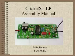
CricketSat LP. Assembly Manual. Mike Fortney 06/26/2006. Index. CricketSat LP (Low Power) Sensor Parts Map CricketSat LP Sensor Assembly Testing Troubleshooting Contact Info. Parts Map. Print out the Parts Map on the following page.

E N D
CricketSat LP Assembly Manual Mike Fortney 06/26/2006
Index • CricketSat LP (Low Power) Sensor Parts Map • CricketSat LP Sensor Assembly • Testing • Troubleshooting • Contact Info
Parts Map • Print out the Parts Map on the following page. • Lay components on respective images to aid in identification during assembly.
CricketSat LP Parts Map 100k Ohm (@ 25C) R1 Thermistor 2.2M Ohm Antenna Wires Notch R2 Red-Red-Green-Gold U3 330k Ohm R3 Orange-Orange-Yellow-Gold - + 18k Ohm R4 Brown-Gray-Orange-Gold SW1 U2 U1 RF Transmitter Switch 5V Regulator Timer IC 33.2k Ohm R5 Orange-Orange-Red-Red-Brown R6 Channel Dependent 33 Ohm Battery Clip Printed Circuit Board R7 Orange-Orange-Black-Gold + 47uF - C1 680 Ohm 47uF + R8 Blue-Gray-Brown-Gold C3 Notch - + Speaker 47uF C4 - U1 Socket + - D1 LED C2 0.01uF White Band - + C5 0.1uF D2 Diode Speaker Jack - C6 + 0.1uF J1 D3 Diode 0.1uF C7
CricketSat Assembly (1 of 16) • Install resistors R2, R3, and R4. Solder and clip leads. • Resistors are not polarized, orientation is not important. • R2, 2.2M Ohm (red-red-green-gold) • R3, 330k Ohm (orange-orange-yellow-gold) • R4, 18k Ohm (brown-gray-orange-gold)
CricketSat Assembly (2 of 16) • Install resistors R5, and R6. Solder and clip leads. • Resistors are not polarized, orientation not important • R5, 33.2k Ohm (orange-orange-red-red-brown) • R6, Resistor value dependent on channel number. It will be the remaining blue resistor in your kit.
CricketSat Assembly (3 of 16) • Install resistors R7, and R8. Solder and clip leads. • Resistors are not polarized, orientation not important • R7, 33 Ohm (orange-orange-black-gold) • R8, 680 Ohm (blue-gray-brown-gold)
CricketSat Assembly (4 of 16) White bands to the right. • Insert diodes D2 and D3 as shown above. • Diodes are polarized. Install with white bands orientated as shown. • Solder and clip leads. • D2 and D3: 1N4001 diodes.
CricketSat Assembly (5 of 16) • Install capacitors C5, C6, and C7. • These capacitors are not polarized. Orientation is not important. • Solder and clip leads. • C5, C6, and C7: 0.1 micro Farad capacitors (104 marking)
CricketSat Assembly (6 of 16) Notch • Install switch and timer IC socket. Solder all pins. No clipping required. • Use masking tape to hold switch in place while soldering. • Make sure that socket pins are in a straight row before inserting into board. Insert socket with the notch pointing up. • Socket will snap into place. • Make sure that all 14 socket pins poke through board before soldering.
CricketSat Assembly (7 of 16) • Install D1, the red light emitting diode (LED). • The LED is polarized. The longer lead is positive (+). Orientation is marked on the circuit board. • Insert LED flush to circuit board. • Solder and clip the leads.
CricketSat Assembly (8 of 16) White bands towards switch White band • Install capacitors C1, C3, and C4 as shown above. • These electrolytic capacitors are polarized. The side with the white band is negative. The positive capacitor lead is longer. • Solder and clip the leads. • C1, C3, and C4: 47 micro Farad capacitors
CricketSat Assembly (9 of 16) • The 5-Volt regulator (U2) is polarized. Orient with the flat surface as shown above. • Insert to this height. • Solder and clip the leads.
CricketSat Assembly (10 of 16) Longer leads for speaker connection • Install J1 2-pin speaker header as shown, longer leads on topside of circuit board. • Use masking tape or rest on table to hold in place while soldering. • Solder shorter leads. Do not clip.
CricketSat Assembly (11 of 16) • Install U3 transmitter module as shown, with the metal can facing the outside of the board. • Use masking tape or rest on table to hold in place while soldering. • Solder and clip leads.
CricketSat Assembly (12 of 16) Solder here Solder here • Route 2” of battery clip wires down through the inner strain relief holes as shown. • The red lead through the hole closest to B+ and the black lead closest to B-. • Push the bare ends back up through the B+ and B- holes. • Pull the wire, removing most of the slack, leaving small loops. • Solder wires in place on the TOP side of the circuit board. Clip the leads. • Pull on the wires to remove any remaining loops.
CricketSat Assembly (13 of 16) • Insert bare end of antenna wires into OUTER holes as shown. • Let circuit board rest on wires, propped in air as shown. • Solder and clip leads. • Route free ends of antenna wires up through inner strain relief holes. • Pull wire until no loop exists below board. • Bend the remaining loop as needed to finish task. • Bend the wires to a 45 degree for best performance.
CricketSat Assembly (14 of 16) • Install capacitor C2 flush to the circuit board as shown to the right. Wiggle and push as necessary. • Orientation for this capacitor is not important. • Solder and clip leads. • C2: 0.01 micro Farad capacitor (103F marking).
CricketSat Assembly (15 of 16) • Install the thermistor, R1 as shown. • Solder and clip leads. • R1: 10k Ohm thermistor at 25degrees C.
CricketSat Assembly (16 of 16) • Install the TS556 timer IC, U1 as shown. • Pins are flared outward. May need to slightly bend inward before inserting into socket. • Check alignment before pressing into place.
Testing • Slide power switch to “OFF” position. • Attach a 9-Volt battery • Slide power switch to “ON” position. • Wait up to 30 seconds for the LED to turn on briefly. • If the LED does not light, proceed to the next slide, “Troubleshooting” • Connect a speaker from the receiver kit to the speaker jack (J1) • You should hear a faint tone periodically. Remove the speaker to enable the LED and RF transmitter to operate. • Test the unit with a CricketSat receiver. You should be able to monitor CricketSat sensors several hundred feet away. • The range for balloon flights may exceed one mile.
Troubleshooting • No sound or lights, no smoke • Insure that slide switch is working properly • Check if battery leads are correctly attached to board, red +, black - • Check if D1 and D2 diodes are properly installed, white band is “-” • Check if U1, U2 and U3 are installed properly • Try another battery • Sound, but no lights • LED may be installed backwards • Lights, but no receiver sound • Turn volume control on receiver to a median setting. Should hear hissing sound.
Contact Info • Michael Fortney • mfortney@cems.uvm.edu • UVM CricketSat Website • http://www.uvm.edu/~cricksat