Jonathan Hirsch, P.E.
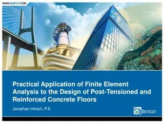
Practical Application of Finite Element Analysis to the Design of Post-Tensioned and Reinforced Concrete Floors. Jonathan Hirsch, P.E. Computer Assisted Design of Concrete Floors. Types of programs available Advantages of each Why specialized finite element software is necessary for PT design.

Jonathan Hirsch, P.E.
E N D
Presentation Transcript
Practical Application of Finite Element Analysis to the Design of Post-Tensioned and Reinforced Concrete Floors Jonathan Hirsch, P.E.
Computer Assisted Design of Concrete Floors • Types of programs available • Advantages of each • Why specialized finite element software is necessary for PT design
Computer Assisted Design of Concrete Floors • The design process using 3-D finite element analysis • Project examples
Types of Programs Available • 2-D strip method • 3-D finite element method • Linear elastic • Non-linear
2-D Strip Method • Structure analyzed with one model per beam, one-way slab, or two-way slab bay • Equivalent frame method used for two-way slabs • Easy to understand behavior • Good for highly repetitive structures
3-D finite element method • Visual modeling / input • Accuracy • continuity effects (elastic reactions) • load path • complicated loads (including lateral) • restraint effects • torsion
3-D finite element method • Graphical presentation of results • Less cumbersome – work with one model instead of numerous • Easier to incorporate changes • Loadings • Concrete geometry • Construction Issues • Low Concrete Strength • Broken Strands
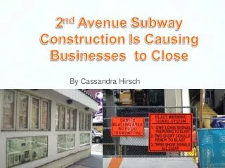
Suncoast Post-Tension Las Olas River Condominiums43 StoryFort Lauderdale, FL
Visual modeling / input • Speed • CAD like interface • Reduce chances for input error • Automatic mesh generation
Accuracy of 3-D FE Analysis • Continuity Effects • Load Path • Complicated Loads • Generally leads to more optimal design
Accuracy of 3-D FE Analysis • Restraining Effects • Torsion
Loads …..Self weight is automatically calculatedSuperimposed loadings easily input
Restraining Effects • Normally ignored by 2-D programs • Can be calculated and accounted for by 3-D finite element programs • Important for serviceability of structure • Important for strength of structure (hyperstatic effects)
Torsion • Normally ignored by 2-D programs (potentially creating a conservative design) • Can exist in 3-D finite element model and therefore should be designed for
Finite Element Basics • Using shell elements to model concrete floors • In plane forces • Out of plane forces • Related in irregular slabs (change of centroid)
Plate Considerations • Resolution of Txy • Integrated forces in equilibrium with nodal loads
Interaction of In Plane/Out of Plane Fx’ = Fx Vxy’ = Vxy Vxz’ = Vxz My’ = My - Fx d Mxy’ = Mxy - Vxy d
Using Shell Elements to Model Beams • Deep beam behavior • Torsion stiffness of beams using shell elements • Transfer of moment through large step
Hyperstatic effects ….. “Complete Secondary (Hyperstatic) Effects” Allan Bommer PTI Journal - January 2004
Post-Tensioning Loadings • Balance Loading • Hyperstatic Loading
The 3-D Finite Element Design Process • Model the structure • Apply the loads • Lay out the tendons (if PT) • Draw design strips (define cross-sections) • Perform the design • Process results