Efficient Link Layer MAC Protocols Overview
670 likes | 709 Vues
Learn about Link Layer Multiple Access Protocols, Ideal MAC Protocol, TDMA, FDMA, CDMA, and Random Access Protocols. Understand their taxonomy and operating principles for efficient network communication.

Efficient Link Layer MAC Protocols Overview
E N D
Presentation Transcript
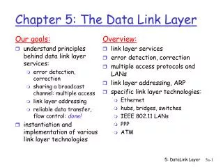
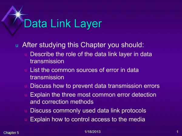
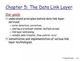
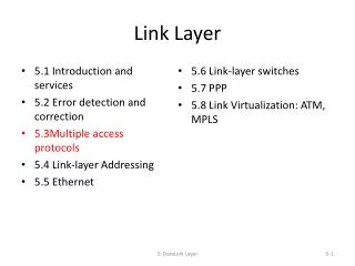
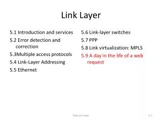
Link layer, LANs: outline • 5.1 Introduction and services • 5.2 Error detection and correction • 5.3Multiple access protocols • 5.4 Link-layer Addressing • 5.5 Ethernet • 5.6 Link-layer switches • 5.7 PPP • 5.8 Link virtualization: MPLS • 5.9 A day in the life of a web request Link Layer
Multiple access links, protocols two types of “links”: • point-to-point • PPP for dial-up access • HDLC (high-level data link control) • point-to-point link between Ethernet switch and host • broadcast (shared wire or medium) • Ethernet • 802.11 wireless LAN shared RF (e.g., 802.11 WiFi) shared RF (satellite) shared wire (e.g., cabled Ethernet) humans at a cocktail party (shared air, acoustical) Link Layer
Multiple access protocols • single shared broadcast channel • two or more simultaneous transmissions by nodes: interference • collision if node receives two or more signals at the same time Multiple Access Protocol (MAC) • distributed algorithm that determines how nodes share channel, • i.e., determine when node can transmit • control signaling messages about channel sharing must use channel itself! • no out-of-band channel for coordination Link Layer
Ideal multiple access protocol given:broadcast channel of rate R bps desire: 1. when one node wants to transmit, it can send at rate R. 2. when M nodes want to transmit, each can send at average rate R/M 3. fully decentralized: • no special node to coordinate transmissions • no synchronization of clocks 4. simple Link Layer
MAC protocols: taxonomy three broad classes: • channel partitioning • divide channel into smaller “pieces” (time slots, frequency, code) • allocate piece to node for exclusive use • random access • channel not divided, allow collisions • “recover” from collisions • controlled access -“taking turns” • nodes take turns, but nodes with more to send can take longer turns Link Layer
MAC protocols: taxonomy Three broad classes: Link Layer
Channel partitioning MAC protocols: TDMA TDMA: time division multiple access • access to channel in "rounds" • each station gets fixed length slot (length = pkt trans time) in each round • unused slots go idle • example: 6-station LAN, 1,3,4 have pkt, slots 2,5,6 idle 6-slot frame 6-slot frame 3 3 4 4 1 1 Link Layer
Channel partitioning MAC protocols: FDMA FDMA: frequency division multiple access • channel spectrum divided into frequency bands • each station assigned fixed frequency band • unused transmission time in frequency bands go idle • example: 6-station LAN, 1,3,4 have pkt, frequency bands 2,5,6 idle time frequency bands FDM cable Link Layer
Channel partitioning MAC protocols: CDMA • used in several wireless broadcast channels (cellular, satellite, etc) standards • unique “code” assigned to each user; i.e., code set partitioning • all users share same frequency, but each user has own “code” sequence to encode data • encoded signal = original data X (code sequence) • decoding = encoded signal X (code sequence) • allows multiple users to “coexist” and transmit simultaneously with minimal interference (if codes are “orthogonal”) Link Layer
Random access protocols • when node has packet to send • transmit at full channel data rate R. • no a priori coordination among nodes • two or more transmitting nodes ➜ “collision”, • random access MAC protocol specifies: • how to detect collisions • how to recover from collisions (e.g., via delayed retransmissions) • examples of random access MAC protocols: • slotted ALOHA • ALOHA • CSMA, CSMA/CD (Ethernet), CSMA/CA (WLAN 802.11) Link Layer
ACK ACK ACK ACK http://en.wikipedia.org/wiki/ALOHAnet ALOHA Network • Developed by Norm Abramson at the Univ. of Hawaii (June, 1971) • fully decentralized protocol 5: DataLink Layer
assumptions: all frames same size time divided into equal size slots (time to transmit 1 frame) nodes start to transmit only slot beginning nodes are synchronized if 2 or more nodes transmit in slot, all nodes detect collision operation: when node obtains fresh frame from its upper layer, transmits it in next slot if no collision: node can send new frame in next slot if collision: node retransmits frame in each subsequent slot with probability “p” until success Slotted ALOHA Link Layer
Pros: single active node can continuously transmit at full rate of channel highly decentralized each node detects collisions and independently decides when to retransmit simple Cons: Collisions wasting slots idle slots clock synchronization 1 1 1 1 node 1 2 2 2 node 2 node 3 3 3 3 C E S C S E C E S Slotted ALOHA efficiency: long-run fraction of successful slots (many nodes, all with many frames to send) at best 37% Link Layer
Pure (unslotted) ALOHA • unslotted Aloha: simpler, no synchronization • when frame first arrives • transmit immediately • collision probability increases: • frame sent at t0 collides with other frames sent in [t0-1,t0+1] efficiency: long-run fraction of successful slots 18% Link Layer
CSMA (carrier sense multiple access) CSMA: listen before transmit: if channel sensed idle: transmit entire frame • if channel sensed busy, defer transmission • human analogy: don’t interrupt others! Link Layer
collisions can still occur: propagation delay means two nodes may not hear each other’s transmission collision: entire packet transmission time wasted distance & propagation delay play role in in determining collision probability When propagation delay is long, wrong decision can happen more CSMA collisions spatial layout of nodes Link Layer
CSMA/CD (collision detection) CSMA/CD:carrier sensing • collisions detected within short time • colliding transmissions aborted, reducing channel wastage • human analogy: the polite conversationalist • collision detection: • easy in wired LANs • measure signal strengths, compare transmitted, received signals • difficult in wireless LANs • received signal strength overwhelmed by local transmission strength Link Layer
CSMA/CD (collision detection) spatial layout of nodes Link Layer
“Taking turns”MAC protocols channel partitioning MAC protocols: • share channel efficiently and fairly at high load • inefficient at low load: delay in channel access, 1/N bandwidth allocated even if only 1 active node! random access MAC protocols • efficient at low load: single node can fully utilize channel • high load: collision can happen more channel wasted “taking turns” protocols look for best of both worlds! Link Layer
data data poll “Taking turns” MAC protocols polling: • master node “invites” slave nodes to transmit in turn • typically used with “dumb” slave devices • concerns: • polling overhead • latency • single point of failure (master) • Bluetooth master slaves Link Layer
“Taking turns” MAC protocols token passing: • control tokenpassed from one node to next sequentially. • token message • concerns: • token overhead • latency • single point of failure (token) • FDDI, IBM Token Ring T (nothing to send) T data Link Layer
Summary of MAC protocols • channel partitioning, by time, frequency or code • Time Division, Frequency Division • random access(dynamic), • ALOHA, S-ALOHA, CSMA, CSMA/CD • carrier sensing: easy in some technologies (wire), hard in others (wireless) • CSMA/CD used in Ethernet • CSMA/CA used in 802.11 • taking turns • polling from central site – bluetooth • token passing - FDDI, IBM token ring Link Layer
Link layer, LANs: outline • 5.1 Introduction and services • 5.2 Error detection and correction • 5.3Multiple access protocols • 5.4 Link-Layer Addressing • 5.5 Ethernet • 5.6 Link-layer switches • 5.7 PPP • 5.8 Link virtualization: MPLS • 5.9 A day in the life of a web request Link Layer
MAC addresses and ARP • 32-bit IP address: • network-layer address for interface • used for layer 3 (network layer) forwarding • MAC (or LAN or physical or Ethernet) address: • function:used ‘locally” to get frame from one interface to another physically-connected interface (in same IP sub-network) • 48 bit MAC address (for most LANs) burned in NIC ROM, also sometimes software settable • e.g.: 1A-2F-BB-76-09-AD hexadecimal (base 16) notation (each “number” represents 4 bits) Link Layer
MAC addresses and ARP each adapter on LAN has unique MAC address 1A-2F-BB-76-09-AD LAN (wired or wireless) adapter 71-65-F7-2B-08-53 58-23-D7-FA-20-B0 0C-C4-11-6F-E3-98 Link Layer
LAN addresses (more) • MAC address allocation administered by IEEE • manufacturer buys portion of MAC address space (to assure uniqueness) • analogy: • MAC address: like Social Security Number • IP address: like postal address • MAC flat address ➜ portability • LAN card can be moved, but its MAC address is not changed • Hierarchical IP address not portable • IP address depends on IP subnet to which node is geographically attached Link Layer
Question: how to determine interface’s MAC address, knowing its IP address? ARP: address resolution protocol ARP table: each IP node (host, router) on LAN has table • IP/MAC address mappings for some LAN nodes: < IP address; MAC address; TTL> • TTL (Time To Live): time after which address mapping will be forgotten (typically 20 min) 137.196.7.78 1A-2F-BB-76-09-AD 137.196.7.23 137.196.7.14 LAN 71-65-F7-2B-08-53 58-23-D7-FA-20-B0 0C-C4-11-6F-E3-98 137.196.7.88 Link Layer
ARP: address resolution protocol • ARP Packet No IP Header Ethernet Header Source MAC (Hardware) Address: … Destination MAC (Hardware) Address: … Link Layer
A wants to send datagram to B A does not know B’s MAC address B’s MAC address not in A’s ARP table. A broadcasts ARP query packet, containing B's IP address dest MAC address = FF-FF-FF-FF-FF-FF all nodes on LAN receive ARP query B receives ARP packet, replies to A with its (B's) MAC address frame sent to A’s MAC address (unicast) A caches (saves) IP-to-MAC address pair in its ARP table until information becomes old (times out) soft state: information that times out (goes away) unless refreshed ARP is “plug-and-play”: nodes create their ARP tables without intervention from net administrator ARP protocol: same LAN Link Layer
111.111.111.110 E6-E9-00-17-BB-4B 222.222.222.222 49-BD-D2-C7-56-2A Addressing: routing to another LAN walkthrough: send datagram from A to B via R • focus on addressing – at IP (datagram) and MAC layer (frame) • assume A knows B’s IP address • assume A knows IP address of first hop router, R (how?) • assume A knows R’s MAC address (how?) B A R 111.111.111.111 74-29-9C-E8-FF-55 222.222.222.220 1A-23-F9-CD-06-9B 222.222.222.221 111.111.111.112 88-B2-2F-54-1A-0F CC-49-DE-D0-AB-7D Link Layer
MAC src: 74-29-9C-E8-FF-55 MAC dest: E6-E9-00-17-BB-4B IP src: 111.111.111.111 IP dest: 222.222.222.222 IP Eth Phy 111.111.111.110 E6-E9-00-17-BB-4B 222.222.222.222 49-BD-D2-C7-56-2A Addressing: routing to another LAN • A creates IP datagram with IP source A, destination B • A creates link-layer frame with R's MAC address as destination MAC address • the frame contains A-to-B IP datagram Netmask is used to determine the destination is in the same subnet B A R 111.111.111.111 74-29-9C-E8-FF-55 222.222.222.220 1A-23-F9-CD-06-9B 222.222.222.221 111.111.111.112 88-B2-2F-54-1A-0F CC-49-DE-D0-AB-7D Link Layer
MAC src: 74-29-9C-E8-FF-55 MAC dest: E6-E9-00-17-BB-4B IP src: 111.111.111.111 IP dest: 222.222.222.222 IP Eth Phy IP src: 111.111.111.111 IP dest: 222.222.222.222 IP Eth Phy 111.111.111.110 E6-E9-00-17-BB-4B 222.222.222.222 49-BD-D2-C7-56-2A Addressing: routing to another LAN • frame sent from A to R • frame received at R, datagram removed, passed up to IP B A R 111.111.111.111 74-29-9C-E8-FF-55 222.222.222.220 1A-23-F9-CD-06-9B 222.222.222.221 111.111.111.112 88-B2-2F-54-1A-0F CC-49-DE-D0-AB-7D Link Layer
IP Eth Phy MAC src: 1A-23-F9-CD-06-9B MAC dest: 49-BD-D2-C7-56-2A IP Eth Phy IP src: 111.111.111.111 IP dest: 222.222.222.222 111.111.111.110 E6-E9-00-17-BB-4B 222.222.222.222 49-BD-D2-C7-56-2A Addressing: routing to another LAN • R forwards datagram with IP source A, destination B • R creates link-layer frame with B's MAC address as destination MAC address • the frame still contains A-to-B IP datagram B A R 111.111.111.111 74-29-9C-E8-FF-55 222.222.222.220 1A-23-F9-CD-06-9B 222.222.222.221 111.111.111.112 88-B2-2F-54-1A-0F CC-49-DE-D0-AB-7D Link Layer
IP Eth Phy MAC src: 1A-23-F9-CD-06-9B MAC dest: 49-BD-D2-C7-56-2A IP Eth Phy IP src: 111.111.111.111 IP dest: 222.222.222.222 111.111.111.110 E6-E9-00-17-BB-4B 222.222.222.222 49-BD-D2-C7-56-2A Addressing: routing to another LAN • R forwards datagram with IP source A, destination B • R creates link-layer frame with B's MAC address as dest, frame contains A-to-B IP datagram B A R 111.111.111.111 74-29-9C-E8-FF-55 222.222.222.220 1A-23-F9-CD-06-9B 222.222.222.221 111.111.111.112 88-B2-2F-54-1A-0F CC-49-DE-D0-AB-7D Link Layer
IP Eth Phy MAC src: 1A-23-F9-CD-06-9B MAC dest: 49-BD-D2-C7-56-2A IP src: 111.111.111.111 IP dest: 222.222.222.222 111.111.111.110 E6-E9-00-17-BB-4B 222.222.222.222 49-BD-D2-C7-56-2A Addressing: routing to another LAN • R forwards datagram with IP source A, destination B • R creates link-layer frame with B's MAC address as dest, frame contains A-to-B IP datagram B A R 111.111.111.111 74-29-9C-E8-FF-55 222.222.222.220 1A-23-F9-CD-06-9B 222.222.222.221 111.111.111.112 88-B2-2F-54-1A-0F CC-49-DE-D0-AB-7D Link Layer
Link layer, LANs: outline • 5.1 Introduction and services • 5.2 Error detection and correction • 5.3Multiple access protocols • 5.4 Link-Layer Addressing • 5.5 Ethernet • 5.6 Link-layer switches • 5.7 PPP • 5.8 Link virtualization: MPLS • 5.9 A day in the life of a web request Link Layer
Ethernet “dominant” wired LAN technology: • cheap $20 for NIC • first widely used LAN technology • simpler, cheaper than token LANs and ATM • kept up with speed race: 10 Mbps – 10 Gbps Metcalfe’s Ethernet sketch Link Layer
Ethernet: physical topology • bus: popular through mid 90s • all nodes in same collision domain (can collide with each other) • star: prevails today • active switchin center • each “spoke” runs a (separate) Ethernet protocol (nodes do not collide with each other) switch star bus: coaxial cable Link Layer
Ethernet frame structure • sending adapter encapsulates IP datagram (or other network layer protocol packet) in Ethernet frame • preamble: • 7 bytes with pattern 10101010 … 10101011 • used to synchronize receiver, sender clock rates type dest. address source address data (payload) CRC preamble Link Layer
Ethernet frame structure (more) • addresses: 6 byte source, destination MAC addresses • if adapter receives frame with matching destination address, or with broadcast address (e.g. ARP packet), it passes data in frame to network layer protocol • otherwise, adapter discards frame • type: indicates higher layer protocol (mostly IP but others possible, e.g., Novell IPX, AppleTalk) • CRC: cyclic redundancy check at receiver • error detected: frame is dropped type dest. address source address data (payload) CRC preamble Link Layer
Ethernet: unreliable, connectionless • connectionless: no handshaking between sending and receiving NICs • unreliable: receiving NIC doesn’t send acks or nacks to sending NIC • data in dropped frames recovered only if initial sender uses higher layer rdt (e.g., TCP), otherwise dropped data lost • Ethernet’s MAC protocol: • unslotted CSMA/CD with exponential backoff Link Layer
1. NIC receives datagram from network layer, creates frame 2-1. If NIC senses channel idle, starts frame transmission. 2-2. If NIC senses channel busy, waits until channel idle, then transmits. 3. If NIC transmits entire frame without detecting another transmission, NIC is done with frame ! Ethernet CSMA/CD algorithm Link Layer
4. If NIC detects another transmission while transmitting, aborts and sends jam signal 5. After aborting, NIC enters exponential backoff: after mth collision, NIC chooses K at random from {0,1,2,3…, 2m-1}. (m = min{n,10}) NIC waits K·512 bit times, returns to Step 2 longer backoff interval with more collisions Ethernet CSMA/CD algorithm Link Layer
Jam Signal: make sure all other transmitters are aware of collision Bit time: .1 microsec for 10 Mbps Ethernet ;for K=1023, wait time is about 50 msec Exponential Backoff: Goal: adapt retransmission attempts to estimated current load heavy load: random wait will be longer first collision: choose K from {0,1}; delay is K· 512 bit transmission times after second collision: choose K from {0,1,2,3}… after ten collisions, choose K from {0,1,2,3,4,…,1023} Ethernet CSMA/CD algorithm (more) better performance than ALOHA: and simple, cheap, decentralized! 5: DataLink Layer
application transport network link physical fiber physical layer copper (twister pair) physical layer 802.3 Ethernet standards: link & physical layers • manydifferent Ethernet standards • common MAC protocol and frame format • different speeds: 2 Mbps, 10 Mbps, 100 Mbps, 1Gbps, 10G bps • different physical layer media: fiber, cable MAC protocol and frame format 100BASE-T2 100BASE-FX 100BASE-TX 100BASE-BX 100BASE-SX 100BASE-T4 Link Layer
Link layer, LANs: outline • 5.1 Introduction and services • 5.2 Error detection and correction • 5.3 Multiple access protocols • 5.4 Link-layer Addressing • 5.5 Ethernet • 5.6 Link-layer switches, LANs • 5.7 PPP • 5.8 Link virtualization: MPLS • 5.9 A day in the life of a web request Link Layer
Ethernet switch • link-layer device • store and forward Ethernet frames • examine incoming frame’s MAC address, selectively forward frame to one-or-more outgoing links when frame is to be forwarded on segment, uses CSMA/CD to access segment • transparent • hosts are unaware of presence of switches • plug-and-play, self-learning • switches do not need to be configured Link Layer
Switch: allow multiplesimultaneous transmissions • hosts have dedicated, direct connection to switch • switches buffer packets • Ethernet protocol used on each incoming link, but no collisions; full duplex • each link is its own collision domain • switching:A-to-A’ and B-to-B’ can transmit simultaneously, without collisions A B C’ 1 2 6 4 5 3 B’ C A’ switch with six interfaces (1,2,3,4,5,6) Link Layer
Switch forwarding table Q:how does switch know A’ reachable via interface 4, B’ reachable via interface 5? A B C’ • A:each switch has a switch table,each entry: • (MAC address of host, interface to reach host, time stamp) • looks like a routing table! 1 2 6 4 5 3 B’ C Q:how are entries created, maintained in switch table? • something like a routing protocol? A’ switch with six interfaces (1,2,3,4,5,6) Link Layer
Source: A Dest: A’ MAC addr interface TTL 60 1 A A A’ Switch: self-learning • switchlearnswhich hosts can be reached through which interfaces • when frame received, switch “learns” location of sender: incoming LAN segment • records sender/location pair in switch table A B C’ 1 2 6 4 5 3 B’ C A’ Switch table (initially empty) Link Layer