DC Analysis of BJT: Exploring BE and CE Loops with Load Line Characteristics
This lecture focuses on DC analysis of Bipolar Junction Transistors (BJTs) by examining the Base-Emitter (BE) and Collector-Emitter (CE) loops. It presents formulas for calculating key parameters like VBE for NPN and VEB for PNP transistors. An example is provided with a PNP transistor, calculating parameters including RC and IE. The concept of load lines in transistor circuits is also introduced, detailing how to use KVL to derive the input and output load lines and find the Q-point of the circuit.

DC Analysis of BJT: Exploring BE and CE Loops with Load Line Characteristics
E N D
Presentation Transcript
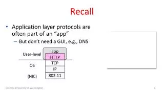
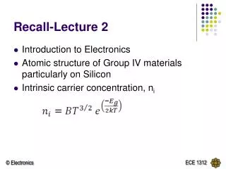
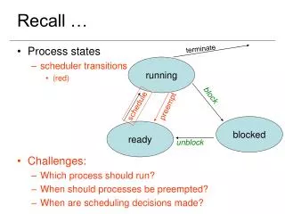
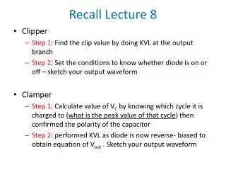
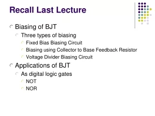
Recall Lecture 10 • DC analysis of BJT • BE Loop (EB Loop) – VBE for npn and VEB for pnp • CE Loop (EC Loop) - VCE for npn and VEC for pnp
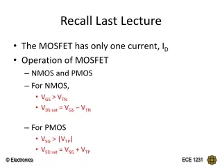
IE EXAMPLE - PNP Given = 75 and VEC = 6V. Find the values of the labelled parameters, RC and IE,
DC analysis of BJT • When node voltages is known, branch current equations can be used. (Va – Vb) / R = I R b a I
BJT Circuits at DC = 0.99 KVL at BE loop: 0.7 + IERE – 4 = 0 IE = 3.3 / 3.3 = 1 mA Hence, IC = IE= 0.99 mA IB = IE – IC = 0.01 mA KVL at CE loop: ICRC + VCE + IERE – 10 = 0 VCE = 10 – 3.3 – 4.653 = 2.047 V
BJT Circuits at DC = 0.99 VC = 5.347 V Hence, VCE = VC – VE = 5.347 – 3.3 = 2.047 V IC = IE IB = IE - IC VBE = 0.7V VB – VE = 0.7V VE = 4 – 0.7 = 3.3 V since VB = 4V VE – 0 = IE 10 - VC = IC 3.3 k 4.7 k
Load Lineand Voltage Transfer Characteristic can be used to visualize the characteristic of the transistor circuits.
Input Load Line – IB versus VBE Derived using B-E loop • The input load line is obtained from Kirchhoff’s voltage law equation around the B-E loop, written as follows: VBE – VBB + IBRB = 0 • Both the load line and the quiescent base current change as either or both VBBand RB change.
IB = -VBE + 4 220k 220k For example; • The input load line is essentially the same as the load line characteristics for diode circuits. VBE – 4 + IB(220k)= 0 y = mx + c • IBQ = 15 μA
Output Load Line – IC versus VCE Derived using C-E loop • For the C-E portion of the circuit, the load line is found by writing Kirchhoff’s voltage law around the C-E loop. We obtain:
IC = -VCE + 10 2k 2k For example; y = mx + c • To find the intersection points setting IC= 0, VCE = VCC = 10 V • setting VCE = 0 IC= VCC / RC = 5 mA Q-point is the intersection of the load line with the iCvsvCE curve, corresponding to the appropriate base current
Example: Calculation and Load Line Calculate the characteristics of a circuit containing an emitter resistor and plot the output load line. For the circuit, let VBE(on) = 0.7 V and β = 75.
Load Line Use KVL at B-E loop
VCE = 12 – IC (1.01) IC = - VCE + 12 1.01 IB = 75.1 A VCE = 12 – 5.63 (1.01) VCE = 6.31 V