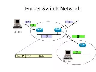
Packet Switch Network
Packet Switch Network. IP. IP. IP. client. IP. IP. IP. IP. TCP. Data. Ether. Server. TCP/IP Layering. DHCP, Mail, WWW, TELNET, FTP. Application. Socket Library. TCP. UDP. Layer 4 / Transport. ARP. RARP. IP. ICMP. Layer 3 / Network. Ethernet. PPP. Layer 2 / Data Link.

Packet Switch Network
E N D
Presentation Transcript
Packet Switch Network IP IP IP client IP IP IP IP TCP Data Ether Server
TCP/IP Layering DHCP, Mail, WWW, TELNET, FTP... Application Socket Library TCP UDP Layer 4 / Transport ARP RARP IP ICMP Layer 3 / Network Ethernet PPP Layer 2 / Data Link Network card Com Layer 1 / Physical
Demultiplexing application application application application ICMP IGMP TCP UDP ARP IP RARP Ethernet incoming frame
data CRC type 6 6 2 64-1500 4 dst src
IP Address 7 bits 24 bits Class A 0 netid hostid 0.1.0.0 to 126.0.0.0 14 bits 16 bits Class B 1 0 netid hostid 128.0.0.0 to 191.255.0.0 21 bits 8 bits Class C 1 1 0 netid hostid 192.0.1.0 to 223.255.255.0 28 bits Class D 1 1 1 0 multicast group ID 224.0.0.0 to 239.255.255.255
IP Address/Physical Address • Static Mapping • IP broadcast address maps to Ethernet broadcast address) • IP Multicast Address maps to Ethernet Multicast Address • lower 23bits of class D IP map into the lower 23bits of Ethernet address 01:00:5e:00:00:00 • Dynamic Mapping • ARP • RARP
ARP • Address Resolution Protocol • RFC-826 • Mapping between IP address and the physical address(such as MAC)
ARP/RARP Packet Format 0 16 31 proto type hard type HLEN op PLEN sender ethernet address sender ether addr sender IP addr target ether addr sender IP addr target ethernet address target IP address Hardware type = 1 : Ethernet Protocol type = 080016: IP address HLEN: hardware address length = 6 : Ethernet MAC address length PLEN: protocol address length = 4 : IP address length OP(operation): 1: ARP request, 2: ARP response, 3: RARP request, 4: RARP response
How it works ? To :140.113.25.6 ‚ ARP IP … ƒ Ethernet † (broadcast) „ Ethernet Ethernet ARP ARP IP 140.113.25.6
IP • Internet Protocol
IP UDP TCP ICMP IGMP IP ARP Ethernet PPP
IP • Internet Protocol • RFC-791 • Unreliable • Connectionless • Dispatch packet to upper protocol • Fragmentation & Assembly • Routing
Packet Format 0 15 16 31 total length TOS HLEN VERS identification fragment offset flag TTL protocol header checksum 20 bytes source IP address destination IP address options(if any) VERS = 4 : IPv4 Protocol HLEN: times of 32-bit, if no options, the HLEN = 5 total length : the total length of the IP datagram, so the data-length of this packet is total length - HLEN *4 TOS: type of service 0 1 2 3 4 5 6 7 precedence D T R unsed precedence: ranging from 0 through 7, indicate the importance of each datagram. allow the router to implement congestion control algorithm D: low delay requests T: high throughput R: high reliability
Packet format • Version : 4 • Header length : number of 32-bit words • TOS : 3-bit precedence, 4 TOS bits, 1 unused • Identification : uniquely identifies each datagram sent by host • flags : more fragments • fragment offset : offset from original datagram • TTL : time to live
Flags & Fragment • Flags : 3 bits 1 2 0 0 DF MF Bit 0: reserved, must be zero Bit 1: (DF) 0 = May Fragment, 1 = Don't Fragment. Bit 2: (MF) 0 = Last Fragment, 1 = More Fragments. • Fragment Offset: 13 bits • Unit : 8 octets (64 bits)
Protocol number • IPPROTO_ICMP 1 IPPROTO_IGMP 2 IPPROTO_GGP 3 IPPROTO_TCP 6 IPPROTO_PUP 12 IPPROTO_UDP 17 IPPROTO_IDP 22 IPPROTO_RSVP 46
Header Checksum • How to calculate ? • checksum field = 0 • sum of 16-bit words • checksum = 1’s complement of sum • How to verify ? • receiver calculate the checksum should be 0xffff (?, 0x0000)
Fragmentation • MTU:Maximum Transmission Unit • Ethernet : 1500 • FDDI : 4352 • IEEE 802.3/802.2 : 1492 • Path MTU • smallest MTU of any data link that packets traverse between the two hosts
ICMP • Internet Control Message Protocol
ICMP ping program ICMP TCP UDP IP
ICMP • Internet Control Message Protocol • RFC-792 • Query Message • Echo request and Echo reply message • Error Message • Destination Unreachable message • Redirect message
internet Ping ping Echo request msg Echo reply msg 0 15 16 31 8 or 0 0 checksum identifier sequence number option data • OPTIONAL Data: is a variable length field that contains data to be returned to the sender. An echo reply always returns exactly the same data as was received in the request. • IDENTIFIER and SEQUENCE NUMBER are used by the sender to match replies to requests.
Destination Unreachable When a router cannot forward or deliver an IP datagram, it sends a destination unreachable message back to the original source. Destination Unreachable msg pkt R internet 0 15 16 31 3 0-12 checksum unused (0) IP header + 64 bits of original IP datagram
Destination Unreachable Code 0 Net Unreachable 1 Host Unreachable 2 Protocol Unreachable 3 Port Unreachable 4 Fragmentation Needed and Don't Fragment was Set 5 Source Route Failed 6 Destination Network Unknown 7 Destination Host Unknown 8 Source Host Isolated 9 Communication with Destination Network is Administratively Prohibited 10 Communication with Destination Host is Administratively Prohibited 11 Destination Network Unreachable for Type of Service 12 Destination Host Unreachable for Type of Service
Redirect R2 R1 ‚ „ ƒ Redirect msg pkt#2 pkt#1 0 15 16 31 5 0-3 checksum router ip address IP header + 64 bits of original IP datagram
Time Exceeded Source Time exceeded msg internet TTL = 1 0 15 16 31 11 0 or 1 checksum Destination unused (0) IP header + 64 bits of original IP datagram
Source Quench Source, send fast Source quench msg internet Buffer full 0 15 16 31 4 0 checksum unused (0) IP header + 64 bits of original IP datagram